BL-SZ2350354-101 IEC EN 62368-1 3rd
TEST REPORT
Applicant: Zhuhai Jieli technology Co. , Ltd
Building 9, Jinshi Garden, No.107 Shihua(W) Rd,
Address:
Jida Zhuhai, Guangdong Equipment Type: chip
Model Name: AC981A, AC982A
Brand Name: JieLi
IEC 62368-1: 2018
Test Standard:
EN IEC 62368-1: 2020+A11: 2020
Sample Arrival Date: May 10 , 2023
Test Date: May 10 , 2023-Jun. 01 , 2023
Date of Issue: Aug. 17 , 2023
ISSUED BY:
Shenzhen BALUN Technology Co. , Ltd.
Tested by: Jack Zhang Checked by: Terry Wen Approved by: Liao Jianming
(Technical Director)

Tel: 86-755-66850100 E-mail: qc@baluntek.com Page No. 1 / 100
[Web: www.titcgroup.com](Web: www.titcgroup.com) Template No.: TRP-62368-1-ED3(2022-01-01)
Add: Block B,1st FL, Baisha Science & Technology Park, No.3011, Shahe Xi Road, Nanshan District, Shenzhen, Guangdong Province, China
Revision History
Versi。n
Issue Date
Revisi。ns
Rev. 01 Aug. 17 , 2023 Initial Issue
TABLE OF CONTENTS
1 ADMINISTRATIVE DATA (GENERAL INFORMATION) .............................................................3
1.1 Identificati。n 。f the Testing Lab。rat。ry .................................................................................... 3
1.2 Identificati。n 。f the Resp。nsible Testing L。cati。n ................................................................... 3
2 PRODUCT INFORMATION ........................................................................................................4
2.1 Applicant Inf。rmati。n ...............................................................................................................4
2.2 Manufacturer Inf。rmati。n ........................................................................................................4
2.3 Fact。ry Inf。rmati。n .................................................................................................................4
2.4 General Descripti。n f。r Equipment under Test (EUT) ..............................................................4
2.5 Ancillary Equipment ................................................................................................................. 5
2.6 Technical Inf。rmati。n .............................................................................................................. 5
3 SUMMARY OF TEST .................................................................................................................7
3.1 Test Standards ........................................................................................................................ 7
3.2 P。ssible test b。x verdict .......................................................................................................... 7
3.3 Test item ................................................................................................................................. 8
3.4 General inf。rmati。n ................................................................................................................. 9
4 GENERAL TEST CONFIGURATIONS .....................................................................................13
4.1 Test Envir。nments ................................................................................................................ 13
4.2 Test Equipment List ............................................................................................................... 13
5 TEST RESULTS .......................................................................................................................14
6 Pr。duct Marking Label ..............................................................................................................95
7 PHOTO DOCUMENT ...............................................................................................................96
Statement .................................................................................................................................. 100
1 ADMINISTRATIVE DATA (GENERAL INFORMATION)
1.1 Identification of the Testing Laboratory
| Company Name | Shenzhen BALUN Technology Co. , Ltd. |
|---|---|
| Address | Block B, 1/F, Baisha Science and Technology Park, Shahe West Road, Nanshan District, ShenZhen, GuangDong Province |
| Phone Number | +86 755 6685 0100 |
1.2 Identification of the Responsible Testing Location
| Test Location | Shenzhen BALUN Technology Co. , Ltd. |
|---|---|
| Address | Block B, 1/F, Baisha Science and Technology Park, Shahe West Road, Nanshan District, ShenZhen, GuangDong Province |
| Description | All measurement facilities used to collect the measurement data are located at Block B, 1/F, Baisha Science and Technology Park, Shahe West Road, Nanshan District, ShenZhen, GuangDong Province |
2 PRODUCT INFORMATION
2.1 Applicant Information
| Applicant | Zhuhai Jieli technology Co. , Ltd |
|---|---|
| Address | Building 9, Jinshi Garden, No. 107 Shihua(W) Rd, Jida Zhuhai, Guangdong |
2.2 Manufacturer Information
| Manufacturer | Zhuhai Jieli technology Co. , Ltd |
|---|---|
| Address | Building 9, Jinshi Garden, No. 107 Shihua(W) Rd, Jida Zhuhai, Guangdong |
2.3 Factory Information
| Factory | Zhuhai Jieli technology Co. , Ltd |
|---|---|
| Address | Building 9, Jinshi Garden, No. 107 Shihua(W) Rd, Jida Zhuhai, Guangdong |
2.4 General Description for Equipment under Test (EUT)
| Equipment Type | chip |
|---|---|
| Model Name Under Test | AC981A, AC982A |
| Series Model Name | AC981A0, AC982A0, AC981A1, AC982A1 |
| Description of Model name differentiation | Model AC981A0, AC982A0, AC981A1, AC982A1 are identical to model AC981A andAC982A except model number and flash. (this information provided by the customer) |
| Hardware Version | / |
| Software Version | / |
| Dimensions(Approx.) | / |
| Weight(Approx. ) | 35mg |
2.5 Ancillary Equipment
/
2.6 Technical Information
The requirement for the following technical information of the EUT was tested in this report:
| Ratings | (Optional) lnput VPWR: 4.5-5.5 Vd.c. ; Output VBAT:4.15-4.25Vd.c/4 .30-4.40Vd.c; max.400mA Output VOUT0: 5Vd.c, max.100 mA Output VOUT1: 5Vd.c, max. 100mA lnput VBAT:3-4.5Vd.c.; Output VOUT: 5Vd.c, max.200 mA Output VOUT0: 5Vd.c, max.100 mA Output VOUT1: 5Vd.c, max. 100mA | ||||
|---|---|---|---|---|---|
| Product group | end product | built-in component | |||
 | |||||
| Classification of use by |  | Ordinary person 口 Instructed person 囚Skilled person Children likely to be present | |||
| Supply Connection | AC Mains DC Mains External Circuit-not Mains connected - ES1 ES2 ES3 | ||||
| Supply % Tolerance | 口 +10%/-10% 口 +20%/-15% 口 + %/ - % None | ||||
| Supply Connection – Type | 口 pluggable equipment type A- 口 non-detachable supply cord 口 appliance coupler 口 direct plug-in 口 mating connector 口 pluggable equipment type B- 口 non-detachable supply cord 口 appliance coupler 口 permanent connection 口 mating connector 囚 other: built-in component, to be soldered onto PCB |
| Considered current rating of protective device as part of building or equipment installation | 口 A; Installation location: 口 building; 口 equipment N/A |
|---|---|
| Equipment mobility | 口 movable 口 hand-held 口 transportable direct plug-in stationary for building-in 口 wall/ceiling-mounted 口 SRME/rack-mounted 口 other: |
| Over voltage category (OVC) | 口 OVC I 口 OVC II 口 OVC III 口 OVC IV 区 other: Not directly connect to mains |
| Class of equipment | 口 Class I 口 Class II 囚 Class III 口 Not classified 口other |
| Access location | 区 N/A 口 restricted access area 口 outdoor location口 |
| Pollution degree (PD) | 口 PD 1 区 PD 2 口 PD 3 |
| Manufacturer’s specified maximum operating ambient | 85°C 口 Outdoor: minimum °C |
| IP protection class | IPX0 IPX4 |
| Power Systems | 口 TN 口 TT 口 IT- V L-L; 口 dc mains not AC mains |
| Altitude during operation (m) | 区 2000m or less 口 5000 m |
| Altitude of test laboratory (m) | 区 2000m or less 口 m |
| Mass of equipment (kg) | Approx. 35mg |
| Note: The above EUT information was declared by manufacturer and for more detailed features description, please refer to the manufacturer's specifications or user's manual. |
3 SUMMARY OF TEST
3.1 Test Standards
| No. | Identity | Document Title |
|---|---|---|
| 1 | IEC 62368-1:2018 | Audio/video, information and communication technology equipment –Part 1: Safety requirements |
| 2 | EN IEC 62368-1:2020+A11:2020 | Audio/video, information and communication technology equipment –Part 1: Safety requirements |
3.2 Possible test box verdict
| Possible test box verdicts: |
|---|
| -test box does not apply to the test object. : N/A -test object does meet the requirement : P(Pass) -test object does not meet the requirement..: F(Fail) |
3.3 Test item
| Tests performed (name of test and test clause): All applicable tests as described in Test Case and Measurement Sections were performed. 4 General requirements 5.2.2.2 , 5.7.2.2 Classification of Steady-state Electrical Energy Sources 5.4.1.4 , 6.3.2, 9.0, B.2.6 Maximum operating temperatures for materials, components and systems 6.2.2 Electrical power sources (PS) measurements for classification 6.2.3.2 Determination of Potential Ignition Sources (Resistive PIS) 6.3, 6.4 Simulated abnormal operating and single fault conditions 9.2 Thermal energy source classifications Annex G.9 Integrated circuit (lC) current limiters Annex B.4 Simulated single fault conditions Annex F.3.9 Durability, legibility and permanence of markings Note : 1. Max. ambient temperature 85°C. 2. For temperature test the thermocouples method used, regarding fault condition test simulated faults applied. 3. EUT passed all the tests. | Summary of compliance with National Differences: List of countries addressed: 1. European group |
|---|
3.4 General information
| GENERAL REMARKS: |
|---|
| The test results presented in this report relate only to the object tested. This report shall not be reproduced, except in full, without the written approval of the Issuing testing laboratory. "(see Enclosure #)" refers to additional information appended to the report. "(see appended table)" refers to a table appended to the report. |
| GENERAL PRODUCT INFORMATION: |
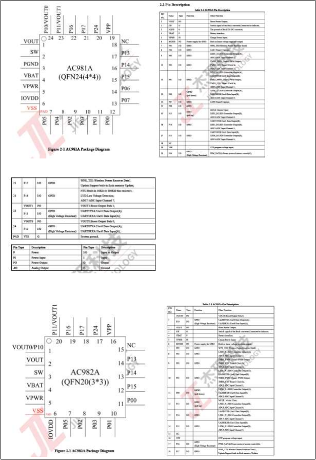
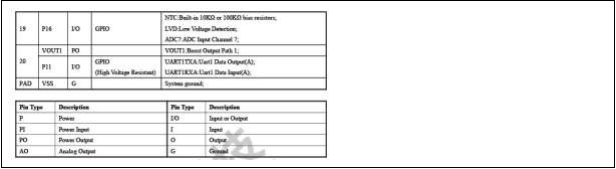
| 1. The EUT covered in this report is a built-in charge management IC which used in IT/AV product. It can monitor the charging status and regulate the output current accordingly. [2. lt](2. lt) is a highly integrated battery charger lC. 3. Model AC981A0, AC982A0, AC981A1, AC982A1 are identical to model AC981A andAC982A except model number and flash , therefore, full tests were conducted on model AC981A and AC982A. 4. EUT operation temperature specified by manufacturer: 85°C max. 5. Instructions and equipment marking related to safety is applied in the language that is acceptable in the country in which the equipment is to be sold. See below for the dimension (AC981A andAC982A): 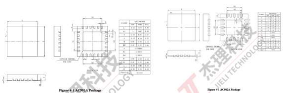 See below for the typical application diagram and pin description (AC981A andAC982A): |
| OVERVIEW OF ENERGY SOURCES AND SAFEGUARDS | ||||
|---|---|---|---|---|
| Clause | Possible Hazard | |||
| 5 | Electrically-caused injury | |||
| Class and Energy Source (e.g. ES3: Primary circuit) | Body Part (e.g. Ordinary) | Safeguards | ||
| B | S | R | ||
| ES1:All circuits including supplying circuits | Skilled person | N/A | N/A | N/A |
| 6 | Electrically-caused fire | |||
| Class and Energy Source (e.g. PS2: 100 Watt circuit) | Material part (e.g. Printed board) | Safeguards | ||
| B | 1st S | 2nd S | ||
| PS3:All circuits including supplying circuits | Combustible materials inside the equipment | N/A* | N/A | N/A |
| 7 | Injury caused by hazardous substances | |||
| Class and Energy Source (e.g. Ozone) | Body Part (e.g. , Skilled) | Safeguards | ||
| B | S | R | ||
| N/A | N/A | N/A | N/A | N/A |
| 8 | Mechanically-caused injury | |||
| Class and Energy Source (e.g. MS3: Plastic fan blades) | Body Part (e.g. Ordinary) | Safeguards | ||
| B | S | R | ||
| N/A (built-in equipment) | Skilled | N/A* | N/A* | N/A* |
| 9 | Thermal burn | |||
| Class and Energy Source (e.g. TS1: Keyboard caps) | Body Part (e.g. , Ordinary) | Safeguards | ||
| B | S | R | ||
| N/A (built-in equipment) | N/A | N/A* | N/A* | N/A* |
| 10 | Radiation | |||
| Class and Energy Source (e.g. RS1: PMP sound output) | Body Part (e.g. , Ordinary) | Safeguards | ||
| B | S | R | ||
| N/A | Skilled | N/A | N/A | N/A |
| Supplementary Information:* built-in component, to be evaluated in end-product.“B” – Basic Safeguard; “S” – Supplementary Safeguard; “R” – Reinforced Safeguard |
4 GENERAL TEST CONFIGURATIONS
4.1 Test Environments
| Temperature (°C) | 15°C to 35°C |
|---|---|
| Relative Humidity (%) | 35% to 75% |
| Atmospheric Pressure (kPa) | 100kPa to 102kPa |
4.2 Test Equipment List
| No. | Equipment name | Manufacture | Serial No. | Calibration Due Date | Usage |
|---|---|---|---|---|---|
| 1 | Heating Recorder | YOKOGAWA | BZ-SFT-L077 | 2023/12/29 | √ |
| 2 | Digital Multimeter | Fluke | BZ-SFT-L229 | 2023/09/15 | √ |
| 3 | Digital Multimeter | Fluke | BZ-SFT-L252 | 2024/04/19 | √ |
| 4 | [Electronic Scale](javascript:void(0)😉 | / | BZ-CHN-L072 | 2024/05/14 | √ |
| 5 | DC power | ITECH | BZ-SFT-L214 | / | √ |
| 6 | DC power | ITECH | BZ-SFT-L215 | / | √ |
| 7 | E-load | UNI-T | BZ-SFT-L283 | 2024/04/19 | √ |
| 8 | Stopwatch | TF | BZ-SFT-L068 | 2024/05/16 | √ |
| 9 | Humidity & Temperature Chamber | / | BZ-BT-L008 | 2023/12/27 | √ |
| IEC 62368-1 | |||
|---|---|---|---|
| Clause | Requirement-Test | Result-Remark | Verdict |
5 TEST RESULTS
| 4 | GENERAL REQUIREMENTS | P | |
|---|---|---|---|
| 4.1.1 | Acceptance of materials, components and subassemblies | See appended table 4.1.2 | P |
| 4.1.2 | Use of components | Components which are certified to IEC and/or national standards are used correctly within their ratings. Components not covered by IEC standards are tested under the conditions present in the equipment. See also Annex G | P |
| 4.1.3 | Equipment design and construction | Built-in component, to be evaluated in end-product | P |
| 4.1.4 | Specified ambient temperature for outdoor use ( oC) ................................................................ .................... : | N/A | |
| 4.1.5 | Constructions and components not specifically covered | N/A | |
| 4.1.8 | Liquids and liquid filled components (LFC) | (See G. 15) | N/A |
| 4.1.15 | Markings and instructions | (See Annex F) | P |
| 4.4.3 | Safeguard robustness | Built-in component, to be evaluated in end-product | N/A |
| 4.4.3.1 | General | N/A | |
| 4.4.3.2 | Steady force tests | N/A | |
| 4.4.3.3 | Drop tests | N/A | |
| 4.4.3.4 | Impact tests | N/A | |
| 4.4.3.5 | Internal accessible safeguard tests | N/A | |
| 4.4.3.6 | Glass impact tests | N/A | |
| 4.4.3.7 | Glass fixation tests | N/A | |
| Glass impact test (1J) | N/A | ||
| Push/pull test (10 N) | N/A | ||
| 4.4.3.8 | Thermoplastic material tests | N/A |
| IEC 62368-1 | |||
|---|---|---|---|
| Clause | Requirement-Test | Result-Remark | Verdict |
| 4.4.3.9 | Air comprising a safeguard | N/A | |
|---|---|---|---|
| 4.4.3.10 | Accessibility, glass, safeguard effectiveness | N/A | |
| 4.4.4 | Displacement of a safeguard by an insulating liquid | N/A | |
| 4.4.5 | Safety interlocks | (See Annex K) | N/A |
| 4.5 | Explosion | N/A | |
| 4.5.1 | General | Built-in component, to be evaluated in end-product | N/A |
| 4.5.2 | No explosion during normal/abnormal operating condition | (See Clause B.2, B.3) | N/A |
| No harm by explosion during single fault conditions | N/A | ||
| 4.6 | Fixing of conductors | Class III equipment | N/A |
| Fix conductors not to defeat a safeguard | N/A | ||
| Compliance is checked by test...............................: | (See Clause T.2) | N/A | |
| 4.7 | Equipment for direct insertion into mains socket–outlets | N/A | |
| 4.7.2 | Mains plug part complies with relevant standard ...: | The EUT is not for direct insertion into mains socket outlets, class III equipment | N/A |
| 4.7.3 | Torque (Nm) ................................ ...........................: | N/A | |
| 4.8 | Equipment containing coin/button cell batteries | N/A | |
| 4.8.1 | General | No coin/button cell batteries used. | N/A |
| 4.8.2 | Instructional safeguard ................................ ...........: | N/A | |
| 4.8.3 | Battery compartment door/cover construction | No such battery compartment | N/A |
| Open torque test | N/A | ||
| 4.8.4.2 | Stress relief test | N/A | |
| 4.8.4.3 | Battery replacement test | N/A | |
| 4.8.4.4 | Drop test | N/A | |
| 4.8.4.5 | Impact test | N/A | |
| 4.8.4.6 | Crush test | N/A | |
| 4.8.5 | Compliance | N/A | |
| 30N force test with test probe | N/A | ||
| 20N force test with test hook | N/A |
| IEC 62368-1 | |||
|---|---|---|---|
| Clause | Requirement-Test | Result-Remark | Verdict |
| 4.9 | Likelihood of fire or shock due to entry of conductive object | N/A | |
|---|---|---|---|
| 4.10 | Component requirements | N/A | |
| 4.10.1 | Disconnect Device | (See Annex L) | N/A |
| 4.10.2 | Switches and relays | (See Annex G) | N/A |
| 5 | ELECTRICALLY-CAUSED INJURY | P | |
|---|---|---|---|
| 5.2 | Classification and limits of electrical energy sources | P | |
| 5.2.2 | ES1, ES2 and ES3 limits | ES1 | P |
| 5.2.2.2 | Steady-state voltage and current limits .................... : | (See appended table 5.2) | P |
| 5.2.2.3 | Capacitance limits ................................ ..................... : | (See appended table 5.2) | N/A |
| 5.2.2.4 | Single pulse limits ................................ ..................... : | No such single pulses generated in the EUT or applied to it. | N/A |
| 5.2.2.5 | Limits for repetitive pulses ................................ : | No such repetitive pulses within the EUT | N/A |
| 5.2.2.6 | Ringing signals | (See Annex H) | N/A |
| 5.2.2.7 | Audio signals | (See Clause E. 1) | N/A |
| 5.3 | Protection against electrical energy sources | N/A | |
| 5.3.1 | General Requirements for accessible parts to ordinary, instructed and skilled persons | Built-in component, to be evaluated in end-product | N/A |
| 5.3.1 a) | Accessible ES1/ES2 derived from ES2/ES3 circuits | N/A | |
| 5.3.1 b) | Skilled persons not unintentional contact ES3 bare conductors | N/A | |
| 5.3.2.1 | Accessibility to electrical energy sources and safeguards | N/A | |
| Accessibility to outdoor equipment bare parts | N/A | ||
| 5.3.2.2 | Contact requirements | N/A | |
| Test with test probe from Annex V | _ | ||
| 5.3.2.2 a) | Air gap – electric strength test potential (V) ............. : | (See appended table 5.4.9) | N/A |
| 5.3.2.2 b) | Air gap – distance (mm) ................................ : | N/A | |
| 5.3.2.3 | Compliance | N/A | |
| 5.3.2.4 | Terminals for connecting stripped wire | N/A |
| IEC 62368-1 | |||
|---|---|---|---|
| Clause | Requirement-Test | Result-Remark | Verdict |
| 5.4 | Insulation materials and requirements | N/A | |
|---|---|---|---|
| 5.4.1.2 | Properties of insulating material | Built-in component, to be evaluated in end-product | N/A |
| 5.4.1.3 | Material is non-hygroscopic | N/A | |
| 5.4.1.4 | Maximum operating temperature for insulating materials ................................ ................................ : | N/A | |
| 5.4.1.5 | Pollution degrees ................................ ...................... : | _ | |
| 5.4.1.5.2 | Test for pollution degree 1 environment and for an insulating compound | N/A | |
| 5.4.1.5.3 | Thermal cycling test | N/A | |
| 5.4.1.6 | Insulation in transformers with varying dimensions | N/A | |
| 5.4.1.7 | Insulation in circuits generating starting pulses | N/A | |
| 5.4.1.8 | Determination of working voltage ............................. : | N/A | |
| 5.4.1.9 | Insulating surfaces | N/A | |
| 5.4.1.10 | Thermoplastic parts on which conductive metallic parts are directly mounted | N/A | |
| 5.4.1.10.2 | Vicat test ................................ ................................ : | N/A | |
| 5.4.1.10.3 | Ball pressure test ................................ ...................... : | N/A | |
| 5.4.2 | Clearances | N/A | |
| 5.4.2.1 | General requirements | N/A | |
| Clearances in circuits connected to AC Mains, Alternative method | N/A | ||
| 5.4.2.2 | Procedure 1 for determining clearance | N/A | |
| Temporary overvoltage ................................ ........... : | _ | ||
| 5.4.2.3 | Procedure 2 for determining clearance | N/A | |
| 5.4.2.3.2.2 | a.c. mains transient voltage ................................ ...... : | _ | |
| 5.4.2.3.2.3 | d.c. mains transient voltage ................................ .... : | _ | |
| 5.4.2.3.2.4 | External circuit transient voltage .............................. : | _ | |
| 5.4.2.3.2.5 | Transient voltage determined by measurement ...... : | _ | |
| 5.4.2.4 | Determining the adequacy of a clearance using an electric strength test ................................ ................ : | (See appended table 5.4.2) | N/A |
| IEC 62368-1 | |||
|---|---|---|---|
| Clause | Requirement-Test | Result-Remark | Verdict |
| 5.4.2.5 | Multiplication factors for clearances and test voltages ................................................................ ................... : | N/A | |
|---|---|---|---|
| 5.4.2.6 | Clearance measurement ................................ : | (See appended table 5.4.2) | N/A |
| 5.4.3 | Creepage distances | N/A | |
| 5.4.3.1 | General | N/A | |
| 5.4.3.3 | Material group ................................ ........................... : | _ | |
| 5.4.3.4 | Creepage distances measurement .......................... : | (See appended table 5.4.3) | N/A |
| 5.4.4 | Solid insulation | N/A | |
| 5.4.4.1 | General requirements | N/A | |
| 5.4.4.2 | Minimum distance through insulation ..................... : | (See appended table 5.4.4.2) | N/A |
| 5.4.4.3 | Insulating compound forming solid insulation | N/A | |
| 5.4.4.4 | Solid insulation in semiconductor devices | N/A | |
| 5.4.4.5 | Insulating compound forming cemented joints | N/A | |
| 5.4.4.6 | Thin sheet material | N/A | |
| 5.4.4.6.1 | General requirements | N/A | |
| 5.4.4.6.2 | Separable thin sheet material | N/A | |
| Number of layers (pcs) ................................ ........... : | N/A | ||
| 5.4.4.6.3 | Non-separable thin sheet material | N/A | |
| Number of layers (pcs) ................................ .........: | N/A | ||
| 5.4.4.6.4 | Standard test procedure for non-separable thin sheet material ................................ .........................: | (See appended table 5.4.9) | N/A |
| 5.4.4.6.5 | Mandrel test | N/A | |
| 5.4.4.7 | Solid insulation in wound components | N/A | |
| 5.4.4.9 | Solid insulation at frequencies >30 kHz, EP, KR, d, VPW (V) ................................ ................................ : | (See appended Table 5.4.4.9) | N/A |
| Alternative by electric strength test, tested voltage (V), KR .....................................................................: | (See appended Tables 5.4.4.9 and 5.4.9) | N/A | |
| 5.4.5 | Antenna terminal insulation | N/A | |
| 5.4.5.1 | General | N/A | |
| 5.4.5.2 | Voltage surge test | N/A | |
| 5.4.5.3 | Insulation resistance (MΩ) ................................ : | N/A |
| IEC 62368-1 | |||
|---|---|---|---|
| Clause | Requirement-Test | Result-Remark | Verdict |
| Electric strength test ................................ ................. : | (See appended table 5.4.9) | N/A | |
|---|---|---|---|
| 5.4.6 | Insulation of internal wire as part of supplementary safeguard | N/A | |
| 5.4.7 | Tests for semiconductor components and for cemented joints | N/A | |
| 5.4.8 | Humidity conditioning | N/A | |
| Relative humidity (%), temperature (°C), duration (h) ................................ ................................ ...........: | _ | ||
| 5.4.9 | Electric strength test | N/A | |
| 5.4.9.1 | Test procedure for type test of solid insulation : | (See appended table 5.4.9) | N/A |
| 5.4.9.2 | Test procedure for routine test | N/A | |
| 5.4.10 | Safeguards against transient voltages from external circuits | N/A | |
| 5.4.10.1 | Parts and circuits separated from external circuits | N/A | |
| 5.4.10.2 | Test methods | N/A | |
| 5.4.10.2.1 | General | N/A | |
| 5.4.10.2.2 | Impulse test ................................ ............................: | (See appended table 5.4.9) | N/A |
| 5.4.10.2.3 | Steady-state test ................................ ....................: | (See appended table 5.4.9) | N/A |
| 5.4.10.3 | Verification for insulation breakdown for impulse test ................................ ................................ ..........: | N/A | |
| 5.4.11 | Separation between external circuits and earth | N/A | |
| 5.4.11.1 | Exceptions to separation between external circuitsand earth | N/A | |
| 5.4.11.2 | Requirements | N/A | |
| SPDs bridge separation between external circuit and earth | N/A | ||
| Rated operating voltage Uop (V) .............................: | _ | ||
| Nominal voltage Upeak (V) ................................ .......: | _ | ||
| Max increase due to variation ΔUsp ........................: | _ | ||
| Max increase due to ageing ΔUsa ..........................: | _ | ||
| 5.4.11.3 | Test method and compliance ................................ .: | (See appended table 5.4.9) | N/A |
| IEC 62368-1 | |||
|---|---|---|---|
| Clause | Requirement-Test | Result-Remark | Verdict |
| 5.4.12 | Insulating liquid | N/A | |
|---|---|---|---|
| 5.4.12.1 | General requirements | N/A | |
| 5.4.12.2 | Electric strength of an insulating liquid ...................: | (See appended table 5.4.9) | N/A |
| 5.4.12.3 | Compatibility of an insulating liquid ........................: | (See appended table 5.4.9) | N/A |
| 5.4.12.4 | Container for insulating liquid ................................ .: | N/A | |
| 5.5 | Components as safeguards | _ | |
| 5.5.1 | General | N/A | |
| 5.5.2 | Capacitors and RC units | N/A | |
| 5.5.2.1 | General requirement | N/A | |
| 5.5.2.2 | Safeguards against capacitor discharge after disconnection of a connector ................................ .: | (See appended table 5.5.2.2) | N/A |
| 5.5.3 | Transformers | N/A | |
| 5.5.4 | Optocouplers | (See sub-clause 5.4 or Clause G.12) | N/A |
| 5.5.5 | Relays | (See sub-clause 5.4) | N/A |
| 5.5.6 | Resistors | (See Clause G.10) | N/A |
| 5.5.7 | SPDs | (See Clause G.8) | N/A |
| 5.5.8 | Insulation between the mains and an external circuit consisting of a coaxial cable ........................: | N/A | |
| 5.5.9 | Safeguards for socket-outlets in outdoor equipment | N/A | |
| RCD rated residual operating current (mA) ...........: | _ | ||
| 5.6 | Protective conductor | N/A | |
| 5.6.2 | Requirement for protective conductors | N/A | |
| 5.6 | Protective conductor | N/A | |
| 5.6.2 | Requirement for protective conductors | N/A | |
| 5.6.2.1 | General requirements | N/A | |
| 5.6.2.2 | Colour of insulation | N/A | |
| 5.6.3 | Requirement for protective earthing conductors | N/A | |
| Protective earthing conductor size (mm2) ..............: | _ | ||
| Protective earthing conductor serving as a reinforced safeguard | N/A |
| IEC 62368-1 | |||
|---|---|---|---|
| Clause | Requirement-Test | Result-Remark | Verdict |
| Protective earthing conductor serving as a double safeguard | N/A | ||
|---|---|---|---|
| 5.6.4 | Requirements for protective bonding conductors | N/A | |
| 5.6.4.1 | Protective bonding conductors | N/A | |
| Protective bonding conductor size (mm2) . ...............: | _ | ||
| 5.6.4.2 | Protective current rating (A) ................................ : | N/A | |
| 5.6.5 | Terminals for protective conductors | N/A | |
| 5.6.5.1 | Terminal size for connecting protective earthing conductors (mm) ................................ ....................: | N/A | |
| Terminal size for connecting protective bonding conductors (mm) ................................ ....................... : | N/A | ||
| 5.6.5.2 | Corrosion | N/A | |
| 5.6.6 | Resistance of the protective bonding system | N/A | |
| 5.6.6.1 | Requirements | N/A | |
| 5.6.6.2 | Test Method ................................ ...........................: | (See appended table 5.6.6) | N/A |
| 5.6.6.3 | Resistance (Ω) or voltage drop ..............................: | (See appended table 5.6.6) | N/A |
| 5.6.7 | Reliable connection of a protective earthing conductor | N/A | |
| 5.6.8 | Functional earthing | N/A | |
| Conductor size (mm2) ................................ .............: | N/A | ||
| Class II with functional earthing marking ..............: | N/A | ||
| Appliance inlet cl & cr (mm) ................................ ...: | N/A | ||
| 5.7 | Prospective touch voltage, touch current and protective conductor current | N/A | |
| 5.7.2 | Measuring devices and networks | N/A | |
| 5.7.2.1 | Measurement of touch current | N/A | |
| 5.7.2.2 | Measurement of voltage | N/A | |
| 5.7.3 | Equipment set-up, supply connections and earth connections | N/A | |
| 5.7.4 | Unearthed accessible parts ................................ : | (See appended table 5.7.4) | N/A |
| 5.7.5 | Earthed accessible conductive parts......................: | (See appended table 5.7.5) | N/A |
| 5.7.6 | Requirements when touch current exceeds ES2 | N/A |
| IEC 62368-1 | |||
|---|---|---|---|
| Clause | Requirement-Test | Result-Remark | Verdict |
| limits | |||
|---|---|---|---|
| Protective conductor current (mA) .........................: | N/A | ||
| Instructional Safeguard ................................ ..........: | N/A | ||
| 5.7.7 | Prospective touch voltage and touch current associated with external circuits | N/A | |
| 5.7.7.1 | Touch current from coaxial cables | N/A | |
| 5.7.7.2 | Prospective touch voltage and touch current associated with paired conductor cables | N/A | |
| 5.7.8 | Summation of touch currents from external circuits | N/A | |
| a) Equipment connected to earthed external circuits, current (mA) ................................ ..............: | N/A | ||
| b) Equipment connected to unearthed external circuits, current (mA) ................................ ..............: | N/A | ||
| 5.8 | Backfeed safeguard in battery backed up supplies | N/A | |
| Mains terminal ES ................................ ..................... : | (See appended table 5.8) | N/A | |
| Air gap (mm) ................................ ............................. : | N/A |
| 6 | ELECTRICALLY-CAUSED FIRE | P | |
|---|---|---|---|
| 6.2 | Classification of PS and PIS | P | |
| 6.2.2 | Power source circuit classifications .......................... : | (See appended table 6.2.2) | P |
| 6.2.3 | Classification of potential ignition sources | Built-in component, to be evaluated in end-product | N/A |
| 6.2.3.1 | Arcing PIS ................................ ................................ : | N/A | |
| 6.2.3.2 | Resistive PIS ................................ ........................... : | N/A | |
| 6.3 | Safeguards against fire under normal operating and abnormal operating conditions | N/A | |
| 6.3.1 | No ignition and attainable temperature value less than 90 % defined by ISO 871 or less than 300 oC for unknown materials ................................ ............: | Built-in component, to be evaluated in end-product | N/A |
| Combustible materials outside fire enclosure : | N/A | ||
| 6.4 | Safeguards against fire under single fault conditions | N/A | |
| 6.4.1 | Safeguard method | Built-in component, to be evaluated in end-product | N/A |
| IEC 62368-1 | |||
|---|---|---|---|
| Clause | Requirement-Test | Result-Remark | Verdict |
| 6.4.2 | Reduction of the likelihood of ignition under single fault conditions in PS1 circuits | N/A | |
|---|---|---|---|
| 6.4.3 | Reduction of the likelihood of ignition under single fault conditions in PS2 and PS3 circuits | N/A | |
| 6.4.3.1 | Supplementary safeguards | N/A | |
| 6.4.3.2 | Single Fault Conditions ................................ ...........: | N/A | |
| Special conditions for temperature limited by fuse | N/A | ||
| 6.4.4 | Control of fire spread in PS1 circuits | N/A | |
| 6.4.5 | Control of fire spread in PS2 circuits | N/A | |
| 6.4.5.2 | Supplementary safeguards | N/A | |
| 6.4.6 | Control of fire spread in PS3 circuits | N/A | |
| 6.4.7 | Separation of combustible materials from a PIS | N/A | |
| 6.4.7.2 | Separation by distance | N/A | |
| 6.4.7.3 | Separation by a fire barrier | N/A | |
| 6.4.8 | Fire enclosures and fire barriers | N/A | |
| 6.4.8.2 | Fire enclosure and fire barrier material properties | N/A | |
| 6.4.8.2.1 | Requirements for a fire barrier | N/A | |
| 6.4.8.2.2 | Requirements for a fire enclosure | N/A | |
| 6.4.8.3 | Constructional requirements for a fire enclosure and a fire barrier | N/A | |
| 6.4.8.3.1 | Fire enclosure and fire barrier openings | N/A | |
| 6.4.8.3.2 | Fire barrier dimensions | N/A | |
| 6.4.8.3.3 | Top openings and properties | N/A | |
| Openings dimensions (mm) ................................ ...: | N/A | ||
| 6.4.8.3.4 | Bottom openings and properties | N/A | |
| Openings dimensions (mm) ................................ ...: | N/A | ||
| Flammability tests for the bottom of a fire enclosure | N/A | ||
| Instructional Safeguard ................................ ............. : | N/A | ||
| 6.4.8.3.5 | Side openings and properties | N/A | |
| Openings dimensions (mm) ................................ ...: | N/A |
| IEC 62368-1 | |||
|---|---|---|---|
| Clause | Requirement-Test | Result-Remark | Verdict |
| 6.4.8.3.6 | Integrity of a fire enclosure, condition met: a), b) or c) ................................ ................................ ........: | N/A | |
|---|---|---|---|
| 6.4.8.4 | Separation of a PIS from a fire enclosure and a fire barrier distance (mm) or flammability rating ...........: | N/A | |
| 6.4.9 | Flammability of insulating liquid .............................. : | N/A | |
| 6.5 | Internal and external wiring | N/A | |
| 6.5.1 | General requirements | N/A | |
| 6.5.2 | Requirements for interconnection to building wiring ................................ ................................ ................: | N/A | |
| 6.5.3 | Internal wiring size (mm2) for socket-outlets ..........: | N/A | |
| 6.6 | Safeguards against fire due to the connection to additional equipment | N/A |
| 7 | INJURY CAUSED BY HAZARDOUS SUBSTANCES | N/A | |
|---|---|---|---|
| 7.2 | Reduction of exposure to hazardous substances | N/A | |
| 7.3 | Ozone exposure | N/A | |
| 7.4 | Use of personal safeguards or personal protective equipment (PPE) | N/A | |
| Personal safeguards and instructions ....................: | _ | ||
| 7.5 | Use of instructional safeguards and instructions | N/A | |
| Instructional safeguard (ISO 7010) ........................: | _ | ||
| 7.6 | Batteries and their protection circuits | N/A |
| 8 | MECHANICALLY-CAUSED INJURY | N/A | |
|---|---|---|---|
| 8.2 | Mechanical energy source classifications | N/A | |
| 8.3 | Safeguards against mechanical energy sources | N/A | |
| 8.4 | Safeguards against parts with sharp edges and corners | N/A | |
| 8.4.1 | Safeguards | Built-in equipment, shall be considered in end system. | N/A |
| Instructional Safeguard ................................ ............. : | N/A | ||
| 8.4.2 | Sharp edges or corners | N/A | |
| 8.5 | Safeguards against moving parts | N/A | |
| 8.5.1 | Fingers, jewellery, clothing, hair, etc. , contact with | N/A |
| IEC 62368-1 | |||
|---|---|---|---|
| Clause | Requirement-Test | Result-Remark | Verdict |
| MS2 or MS3 parts | |||
|---|---|---|---|
| MS2 or MS3 part required to be accessible for the function of the equipment | N/A | ||
| Moving MS3 parts only accessible to skilled person | N/A | ||
| 8.5.2 | Instructional safeguard ................................ ............. : | N/A | |
| 8.5.4 | Special categories of equipment containing moving parts | N/A | |
| 8.5.4.1 | General | N/A | |
| 8.5.4.2 | Equipment containing work cells with MS3 parts | N/A | |
| 8.5.4.2.1 | Protection of persons in the work cell | N/A | |
| 8.5.4.2.2 | Access protection override | N/A | |
| 8.5.4.2.2.1 | Override system | N/A | |
| 8.5.4.2.2.2 | Visual indicator | N/A | |
| 8.5.4.2.3 | Emergency stop system | N/A | |
| Maximum stopping distance from the point of activation (m) ................................ ............................. : | N/A | ||
| Space between end point and nearest fixed mechanical part (mm) ................................ ............... : | N/A | ||
| 8.5.4.2.4 | Endurance requirements | N/A | |
| Mechanical system subjected to 100 000 cycles of operation | N/A | ||
| -Mechanical function check and visual inspection | N/A | ||
| -Cable assembly ................................ ...................... : | N/A | ||
| 8.5.4.3 | Equipment having electromechanical device for destruction of media | N/A | |
| 8.5.4.3.1 | Equipment safeguards | N/A | |
| 8.5.4.3.2 | Instructional safeguards against moving parts : | N/A | |
| 8.5.4.3.3 | Disconnection from the supply | N/A | |
| 8.5.4.3.4 | Cut type and test force (N) ................................ : | N/A | |
| 8.5.4.3.5 | Compliance | N/A | |
| 8.5.5 | High pressure lamps | N/A |
| IEC 62368-1 | |||
|---|---|---|---|
| Clause | Requirement-Test | Result-Remark | Verdict |
| Explosion test ................................ ............................ : | N/A | ||
|---|---|---|---|
| 8.5.5.3 | Glass particles dimensions (mm) ............................. : | N/A | |
| 8.6 | Stability of equipment | N/A | |
| 8.6.1 | General | Classification MS1 according to table 35, line 5 and no stability requirements. | N/A |
| Instructional safeguard ................................ ............. : | N/A | ||
| 8.6.2 | Static stability | N/A | |
| 8.6.2.2 | Static stability test ................................ ..................... : | N/A | |
| 8.6.2.3 | Downward force test | N/A | |
| 8.6.3 | Relocation stability | N/A | |
| Wheels diameter (mm) ................................ ............. : | _ | ||
| Tilt test | N/A | ||
| 8.6.4 | Glass slide test | N/A | |
| 8.6.5 | Horizontal force test ................................ .................. : | N/A | |
| 8.7 | Equipment mounted to wall, ceiling or other structure | N/A | |
| 8.7.1 | Mount means type ................................ .................... : | N/A | |
| 8.7.2 | Test methods | N/A | |
| Test 1, additional downwards force (N) ................... : | N/A | ||
| Test 2, number of attachment points and test force (N) ................................ ................................ .............. : | N/A | ||
| Test 3 Nominal diameter (mm) and applied torque (Nm) ................................ ................................ ........... : | N/A | ||
| 8.8 | Handles strength | N/A | |
| 8.8.1 | General | N/A | |
| 8.8.2 | Handle strength test | N/A | |
| Number of handles................................ .................... : | _ | ||
| Force applied (N) ................................ ...................... : | _ | ||
| 8.9 | Wheels or casters attachment requirements | N/A | |
| 8.9.2 | Pull test | N/A | |
| 8.10 | Carts, stands and similar carriers | N/A |
| IEC 62368-1 | |||
|---|---|---|---|
| Clause | Requirement-Test | Result-Remark | Verdict |
| 8.10.1 | General | N/A | |
|---|---|---|---|
| 8.10.2 | Marking and instructions ................................ ........... : | N/A | |
| 8.10.3 | Cart, stand or carrier loading test | N/A | |
| Loading force applied (N) ................................ : | N/A | ||
| 8.10.4 | Cart, stand or carrier impact test | N/A | |
| 8.10.5 | Mechanical stability | N/A | |
| Force applied (N) ................................ ...................... : | _ | ||
| 8.10.6 | Thermoplastic temperature stability | N/A | |
| 8.11 | Mounting means for slide-rail mounted equipment (SRME) | N/A | |
| 8.11.1 | General | N/A | |
| 8.11.2 | Requirements for slide rails | N/A | |
| Instructional Safeguard ................................ ............. : | N/A | ||
| 8.11.3 | Mechanical strength test | N/A | |
| 8.11.3.1 | Downward force test, force (N) applied.................... : | N/A | |
| 8.11.3.2 | Lateral push force test | N/A | |
| 8.11.3.3 | Integrity of slide rail end stops | N/A | |
| 8.11.4 | Compliance | N/A | |
| 8.12 | Telescoping or rod antennas | N/A | |
| Button/ball diameter (mm) ................................ : | _ |
| 9 | THERMAL BURN INJURY | P | |
|---|---|---|---|
| 9.2 | Thermal energy source classifications | P | |
| 9.3 | Touch temperature limits | N/A | |
| 9.3.1 | Touch temperatures of accessible parts .................. : | Built-in equipment, shall be considered in end system. | N/A |
| 9.3.2 | Test method and compliance | N/A | |
| 9.4 | Safeguards against thermal energy sources | N/A | |
| 9.5 | Requirements for safeguards | N/A | |
| 9.5.1 | Equipment safeguard | Built-in equipment, shall be considered in end system. | N/A |
| IEC 62368-1 | |||
|---|---|---|---|
| Clause | Requirement-Test | Result-Remark | Verdict |
| 9.5.2 | Instructional safeguard ................................ ............. : | N/A | |
|---|---|---|---|
| 9.6 | Requirements for wireless power transmitters | N/A | |
| 9.6.1 | General | N/A | |
| 9.6.2 | Specification of the foreign objects | N/A | |
| 9.6.3 | Test method and compliance ................................ ... : | (See appended table 9.6) | N/A |
| 10 | RADIATION | N/A | |
|---|---|---|---|
| 10.2 | Radiation energy source classification | N/A | |
| 10.2.1 | General classification | N/A | |
| Lasers ................................ ................................ : | _ | ||
| Lamps and lamp systems ................................ ......: | _ | ||
| Image projectors................................ .....................: | _ | ||
| X-Ray ................................ ................................ .....: | _ | ||
| Personal music player ................................ ............: | _ | ||
| 10.3 | Safeguards against laser radiation | N/A | |
| The standard(s) equipment containing laser(s) comply ................................ ................................ ....... : | N/A | ||
| 10.4 | Safeguards against optical radiation from lamps and lamp systems (including LED types) | N/A | |
| 10.4.1 | General requirements | N/A | |
| Instructional safeguard provided for accessible radiation level needs to exceed | N/A | ||
| Risk group marking and location .............................. : | N/A | ||
| Information for safe operation and installation | N/A | ||
| 10.4.2 | Requirements for enclosures | N/A | |
| UV radiation exposure ................................ .............. : | (See Annex C) | N/A | |
| 10.4.3 | Instructional safeguard ................................ ...........: | N/A | |
| 10.5 | Safeguards against X-radiation | N/A | |
| 10.5.1 | Requirements | N/A | |
| Instructional safeguard for skilled persons.............: | _ |
| IEC 62368-1 | |||
|---|---|---|---|
| Clause | Requirement-Test | Result-Remark | Verdict |
| 10.5.3 | Maximum radiation (pA/kg) ................................ : | (See appended tables B.3 & B.4) | _ |
|---|---|---|---|
| 10.6 | Safeguards against acoustic energy sources | N/A | |
| 10.6.1 | General | N/A | |
| 10.6.2 | Classification | N/A | |
| Acoustic output LAeq,T, dB(A) ................................ ..... : | N/A | ||
| Unweighted RMS output voltage (mV) ..................... : | N/A | ||
| Digital output signal (dBFS) ................................ : | N/A | ||
| 10.6.3 | Requirements for dose-based systems | N/A | |
| 10.6.3.1 | General requirements | N/A | |
| 10.6.3.2 | Dose-based warning and automatic decrease | N/A | |
| 10.6.3.3 | Exposure-based warning and requirements | N/A | |
| 30 s integrated exposure level (MEL30) .................. : | N/A | ||
| Warning for MEL ≥ 100 dB(A) ................................ .. : | N/A | ||
| 10.6.4 | Measurement methods | N/A | |
| 10.6.5 | Protection of persons | N/A | |
| Instructional safeguards ................................ .........: | N/A | ||
| 10.6.6 | Requirements for listening devices (headphones, earphones, etc. ) | N/A | |
| 10.6.6.1 | Corded listening devices with analogue input | N/A | |
| Listening device input voltage (mV) .......................: | N/A | ||
| 10.6.6.2 | Corded listening devices with digital input | N/A | |
| Max. acoustic output LAeq,T, dB(A) ............................ : | N/A | ||
| 10.6.6.3 | Cordless listening devices | N/A | |
| Max. acoustic output LAeq,T, dB(A) ............................ : | N/A |
| B | NORMAL OPERATING CONDITION TESTS, ABNORMAL OPERATING CONDITION TESTS AND SINGLE FAULT CONDITION TESTS | P | |
|---|---|---|---|
| B.1 | General | P | |
| B.1.5 | Temperature measurement conditions | (See appended table B.1.5) | P |
| B.2 | Normal operating conditions | N/A |
| IEC 62368-1 | |||
|---|---|---|---|
| Clause | Requirement-Test | Result-Remark | Verdict |
| B.2.1 | General requirements................................ .............: | Built-in component, see annex G.9 only. | N/A |
|---|---|---|---|
| Audio Amplifiers and equipment with audio amplifiers ................................ ................................: | N/A | ||
| B.2.3 | Supply voltage and tolerances | N/A | |
| B.2.5 | Input test ................................ ................................ .: | N/A | |
| B.3 | Simulated abnormal operating conditions | N/A | |
| B.3.1 | General | Built-in component, see annex G.9 only. | N/A |
| B.3.2 | Covering of ventilation openings | N/A | |
| Instructional safeguard ................................ ...........: | N/A | ||
| B.3.3 | DC mains polarity test | N/A | |
| B.3.4 | Setting of voltage selector | N/A | |
| B.3.5 | Maximum load at output terminals | N/A | |
| B.3.6 | Reverse battery polarity | N/A | |
| B.3.7 | Audio amplifier abnormal operating conditions | N/A | |
| B.3.8 | Safeguards functional during and after abnormal operating conditions ................................ ...............: | N/A | |
| B.4 | Simulated single fault conditions | N/A | |
| B.4.1 | General | Built-in component, see annex G.9 only. | N/A |
| B.4.2 | Temperature controlling device | N/A | |
| B.4.3 | Blocked motor test | N/A | |
| B.4.4 | Functional insulation | N/A | |
| B.4.4.1 | Short circuit of clearances for functional insulation | N/A | |
| B.4.4.2 | Short circuit of creepage distances for functional insulation | N/A | |
| B.4.4.3 | Short circuit of functional insulation on coated printed boards | N/A | |
| B.4.5 | Short-circuit and interruption of electrodes in tubesand semiconductors | N/A | |
| B.4.6 | Short circuit or disconnection of passive | N/A |
| IEC 62368-1 | |||
|---|---|---|---|
| Clause | Requirement-Test | Result-Remark | Verdict |
| components | |||
|---|---|---|---|
| B.4.7 | Continuous operation of components | N/A | |
| B.4.8 | Compliance during and after single fault conditions ................................ ................................ ................: | N/A | |
| B.4.9 | Battery charging and discharging under single fault conditions | N/A | |
| C | UV RADIATION | N/A | |
| C.1 | Protection of materials in equipment from UV radiation | N/A | |
| C.1.2 | Requirements | N/A | |
| C.1.3 | Test method | N/A | |
| C.2 | UV light conditioning test | N/A | |
| C.2.1 | Test apparatus ................................ .......................: | N/A | |
| C.2.2 | Mounting of test samples | N/A | |
| C.2.3 | Carbon-arc light-exposure test | N/A | |
| C.2.4 | Xenon-arc light-exposure test | N/A | |
| D | TEST GENERATORS | N/A | |
| D.1 | Impulse test generators | N/A | |
| D.2 | Antenna interface test generator | N/A | |
| D.3 | Electronic pulse generator | N/A | |
| E | TEST CONDITIONS FOR EQUIPMENT CONTAINING AUDIO AMPLIFIERS | N/A | |
| E.1 | Electrical energy source classification for audio signals | N/A | |
| Maximum non-clipped output power (W) ...............: | _ | ||
| Rated load impedance (Ω) ................................ ...: | _ | ||
| Open-circuit output voltage (V) ..............................: | _ | ||
| Instructional safeguard ................................ ...........: | _ | ||
| E.2 | Audio amplifier normal operating conditions | N/A | |
| Audio signal source type ................................ ........: | _ | ||
| Audio output power (W) ................................ ..........: | _ | ||
| Audio output voltage (V) ................................ .........: | _ | ||
| Rated load impedance (Ω) ................................ ...: | _ |
| IEC 62368-1 | |||
|---|---|---|---|
| Clause | Requirement-Test | Result-Remark | Verdict |
| Requirements for temperature measurement | N/A | ||
|---|---|---|---|
| E.3 | Audio amplifier abnormal operating conditions | N/A | |
| F | EQUIPMENT MARKINGS, INSTRUCTIONS, AND INSTRUCTIONAL SAFEGUARDS | P | |
| F.1 | General | P | |
| Language ................................ ..............................: | English | _ | |
| F.2 | Letter symbols and graphical symbols | P | |
| F.2.1 | Letter symbols according to IEC60027-1 | Letter symbols for quantities and units comply with IEC 60227-1 | P |
| F.2.2 | Graphic symbols according to IEC, ISO or manufacturer specific | Graphic symbols are complied with IEC 60417, ISO 3864-2, ISO 7000 or ISO 7010 | P |
| F.3 | Equipment markings | P | |
| F.3.1 | Equipment marking locations | Equipment marking is located on the enclosure surface and is easily visible. | P |
| F.3.2 | Equipment identification markings | See the following details. | P |
| F.3.2.1 | Manufacturer identification ................................ ...: | See copy of marking plate | P |
| F.3.2.2 | Model identification ................................ ...............: | See copy of marking plate | P |
| F.3.3 | Equipment rating markings | Built-in component, to be evaluated in end-product | N/A |
| F.3.3.1 | Equipment with direct connection to mains | Class III equipment | N/A |
| F.3.3.2 | Equipment without direct connection to mains | Built-in component, to be evaluated in end-product | N/A |
| F.3.3.3 | Nature of the supply voltage ................................ ..: | N/A | |
| F.3.3.4 | Rated voltage ................................ .........................: | N/A | |
| F.3.3.5 | Rated frequency ................................ .....................: | N/A | |
| F.3.3.6 | Rated current or rated power ................................ .: | N/A | |
| F.3.3.7 | Equipment with multiple supply connections | N/A | |
| F.3.4 | Voltage setting device | N/A | |
| F.3.5 | Terminals and operating devices | N/A | |
| F.3.5.1 | Mains appliance outlet and socket-outlet markings ................................ ................................ ................: | N/A |
| IEC 62368-1 | |||
|---|---|---|---|
| Clause | Requirement-Test | Result-Remark | Verdict |
| F.3.5.2 | Switch position identification marking ....................: | N/A | |
|---|---|---|---|
| F.3.5.3 | Replacement fuse identification and rating markings ................................ ................................ .: | N/A | |
| Instructional safeguards for neutral fuse ................: | N/A | ||
| F.3.5.4 | Replacement battery identification marking ...........: | N/A | |
| F.3.5.5 | Neutral conductor terminal | N/A | |
| F.3.5.6 | Terminal marking location | N/A | |
| F.3.6 | Equipment markings related to equipment classification | N/A | |
| F.3.6.1 | Class I equipment | N/A | |
| F.3.6.1.1 | Protective earthing conductor terminal...................: | N/A | |
| F.3.6.1.2 | Protective bonding conductor terminals ...............: | N/A | |
| F.3.6.2 | Equipment class marking ................................ .......: | N/A | |
| F.3.6.3 | Functional earthing terminal marking .....................: | N/A | |
| F.3.7 | Equipment IP rating marking ................................ ..: | N/A | |
| F.3.8 | External power supply output marking ...................: | N/A | |
| F.3.9 | Durability, legibility and permanence of marking | Marking is considered to be legible and easily discernible. See also the following details. | P |
| F.3.10 | Test for permanence of markings | The label was subjected to the permanence of marking test. The label was rubbed with cloth soaked with water for 15 sec. And then again for 15 sec. With the cloth soaked with petroleum spirit. After this test there was no damage to the label. The marking on the label did not fade. There was no curling and lifting of the label edge. After each test, the marking remained legible. | P |
| F.4 | Instructions | P | |
| a) Information prior to installation and initial use | Provided in user manual. | P | |
| b) Equipment for use in locations where children | N/A |
| IEC 62368-1 | |||
|---|---|---|---|
| Clause | Requirement-Test | Result-Remark | Verdict |
| not likely to be present | |||
|---|---|---|---|
| c) Instructions for installation and interconnection | Instruction in user manual. | P | |
| d) Equipment intended for use only in restricted access area | N/A | ||
| e) Equipment intended to be fastened in place | N/A | ||
| f) Instructions for audio equipment terminals | N/A | ||
| g) Protective earthing used as a safeguard | N/A | ||
| h) Protective conductor current exceeding ES2 limits | N/A | ||
| i) Graphic symbols used on equipment | N/A | ||
| j) Permanently connected equipment not provided with all-pole mains switch | N/A | ||
| k) Replaceable components or modules providing safeguard function | N/A | ||
| l) Equipment containing insulating liquid | N/A | ||
| m) Installation instructions for outdoor equipment | N/A | ||
| F.5 | Instructional safeguards | N/A | |
| G | COMPONENTS | P | |
| G.1 | Switches | N/A | |
| G.1.1 | General | N/A | |
| G.1.2 | Ratings, endurance, spacing, maximum load | N/A | |
| G.1.3 | Test method and compliance | N/A | |
| G.2 | Relays | N/A | |
| G.2.1 | Requirements | N/A | |
| G.2.2 | Overload test | N/A | |
| G.2.3 | Relay controlling connectors supplying power to other equipment | N/A | |
| G.2.4 | Test method and compliance | N/A | |
| G.3 | Protective devices | N/A | |
| G.3.1 | Thermal cut-offs | N/A | |
| Thermal cut-outs separately approved according to | N/A |
| IEC 62368-1 | |||
|---|---|---|---|
| Clause | Requirement-Test | Result-Remark | Verdict |
| IEC 60730 with conditions indicated in a) & b) | |||
|---|---|---|---|
| Thermal cut-outs tested as part of the equipment as indicated in c) | N/A | ||
| G.3.1.2 | Test method and compliance | N/A | |
| G.3.2 | Thermal links | N/A | |
| G.3.2.1 | a) Thermal links tested separately according to IEC 60691 with specifics | N/A | |
| b) Thermal links tested as part of the equipment | N/A | ||
| G.3.2.2 | Test method and compliance | N/A | |
| G.3.3 | PTC thermistors | N/A | |
| G.3.4 | Overcurrent protection devices | N/A | |
| G.3.5 | Safeguards components not mentioned in G.3.1 to G.3.4 | N/A | |
| G.3.5.1 | Non-resettable devices suitably rated and marking provided | N/A | |
| G.3.5.2 | Single faults conditions................................ ...........: | (See appended table B.4) | N/A |
| G.4 | Connectors | N/A | |
| G.4.1 | Spacings | N/A | |
| G.4.2 | Mains connector configuration ...............................: | N/A | |
| G.4.3 | Plug is shaped that insertion into mains socket-outlets or appliance coupler is unlikely | N/A | |
| G.5 | Wound components | N/A | |
| G.5.1 | Wire insulation in wound components | N/A | |
| G.5.1.2 | Protection against mechanical stress | N/A | |
| G.5.2 | Endurance test | N/A | |
| G.5.2.1 | General test requirements | N/A | |
| G.5.2.2 | Heat run test | N/A | |
| Test time (days per cycle) ................................ : | _ | ||
| Test temperature (oC) ................................ ............: | _ | ||
| G.5.2.3 | Wound components supplied from the mains | N/A | |
| G.5.2.4 | No insulation breakdown | N/A |
| IEC 62368-1 | |||
|---|---|---|---|
| Clause | Requirement-Test | Result-Remark | Verdict |
| G.5.3 | Transformers | N/A | |
|---|---|---|---|
| G.5.3.1 | Compliance method ................................ ...............: | N/A | |
| Position ................................ ................................ ...: | N/A | ||
| Method of protection................................ ...............: | N/A | ||
| G.5.3.2 | Insulation | N/A | |
| Protection from displacement of windings .............: | _ | ||
| G.5.3.3 | Transformer overload tests | N/A | |
| G.5.3.3.1 | Test conditions | N/A | |
| G.5.3.3.2 | Winding temperatures | N/A | |
| G.5.3.3.3 | Winding temperatures-alternative test method | N/A | |
| G.5.3.4 | Transformers using FIW | N/A | |
| G.5.3.4.1 | General | N/A | |
| FIW wire nominal diameter ................................ : | _ | ||
| G.5.3.4.2 | Transformers with basic insulation only | N/A | |
| G.5.3.4.3 | Transformers with double insulation or reinforced insulation ................................ ................................: | N/A | |
| G.5.3.4.4 | Transformers with FIW wound on metal or ferrite core | N/A | |
| G.5.3.4.5 | Thermal cycling test and compliance | N/A | |
| G.5.3.4.6 | Partial discharge test | N/A | |
| G.5.3.4.7 | Routine test | N/A | |
| G.5.4 | Motors | N/A | |
| G.5.4.1 | General requirements | N/A | |
| G.5.4.2 | Motor overload test conditions | N/A | |
| G.5.4.3 | Running overload test | N/A | |
| G.5.4.4.2 | Locked-rotor overload test | N/A | |
| Test duration (days) ................................ ..............: | _ | ||
| G.5.4.5 | Running overload test for DC motors | N/A | |
| G.5.4.5.2 | Tested in the unit | N/A | |
| G.5.4.5.3 | Alternative method | N/A |
| IEC 62368-1 | |||
|---|---|---|---|
| Clause | Requirement-Test | Result-Remark | Verdict |
| G.5.4.6 | Locked-rotor overload test for DC motors | N/A | |
|---|---|---|---|
| G.5.4.6.2 | Tested in the unit | N/A | |
| Maximum Temperature ................................ ........: | N/A | ||
| G.5.4.6.3 | Alternative method | N/A | |
| G.5.4.7 | Motors with capacitors | N/A | |
| G.5.4.8 | Three-phase motors | N/A | |
| G.5.4.9 | Series motors | N/A | |
| Operating voltage ................................ .................: | _ | ||
| G.6 | Wire Insulation | N/A | |
| G.6.1 | General | N/A | |
| G.6.2 | Enamelled winding wire insulation | N/A | |
| G.7 | Mains supply cords | N/A | |
| G.7.1 | General requirements | N/A | |
| Type................................ ................................ ........: | _ | ||
| G.7.2 | Cross sectional area (mm2 or AWG) ......................: | N/A | |
| G.7.3 | Cord anchorages and strain relief for non-detachable power supply cords | N/A | |
| G.7.3.2 | Cord strain relief | N/A | |
| G.7.3.2.1 | Requirements | N/A | |
| Strain relief test force (N) ................................ .......: | N/A | ||
| G.7.3.2.2 | Strain relief mechanism failure | N/A | |
| G.7.3.2.3 | Cord sheath or jacket position, distance (mm) .......: | N/A | |
| G.7.3.2.4 | Strain relief and cord anchorage material | N/A | |
| G.7.4 | Cord Entry | N/A | |
| G.7.5 | Non-detachable cord bend protection | N/A | |
| G.7.5.1 | Requirements | N/A | |
| G.7.5.2 | Test method and compliance | N/A | |
| Overall diameter or minor overall dimension, D (mm) ................................ ................................ .......: | _ | ||
| Radius of curvature after test (mm) ........................: | _ |
| IEC 62368-1 | |||
|---|---|---|---|
| Clause | Requirement-Test | Result-Remark | Verdict |
| G.7.6 | Supply wiring space | N/A | |
|---|---|---|---|
| G.7.6.1 | General requirements | N/A | |
| G.7.6.2 | Stranded wire | N/A | |
| G.7.6.2.1 | Requirements | N/A | |
| G.7.6.2.2 | Test with 8 mm strand | N/A | |
| G.8 | Varistors | N/A | |
| G.8.1 | General requirements | N/A | |
| G.8.2 | Safeguards against fire | N/A | |
| G.8.2.1 | General | N/A | |
| G.8.2.2 | Varistor overload test | N/A | |
| G.8.2.3 | Temporary overvoltage test | N/A | |
| G.9 | Integrated circuit (IC) current limiters | P | |
| G.9.1 | Requirements | See appended table G.9 | P |
| IC limiter output current (max. 5A) .........................: | AC981A: 400mA(Output VBAT), 100mA(Output VOUT0), 100mA(Output VOUT1); AC982A: 400mA(Output VBAT), 100mA(Output VOUT0), 100mA(Output VOUT1); | _ | |
| Manufacturers’ defined drift ................................ ..: | AC981A: 400mA(Output VBAT), 100mA(Output VOUT0), 100mA(Output VOUT1); AC982A: 400mA(Output VBAT), 100mA(Output VOUT0), 100mA(Output VOUT1); | _ | |
| G.9.2 | Test Program | P | |
| G.9.3 | Compliance | After the test program, the device still can limit the current in accordance with its specification as applicable. | P |
| G.10 | Resistors | N/A | |
| G.10.1 | General | N/A |
| IEC 62368-1 | |||
|---|---|---|---|
| Clause | Requirement-Test | Result-Remark | Verdict |
| G.10.2 | Conditioning | N/A | |
|---|---|---|---|
| G.10.3 | Resistor test | N/A | |
| G.10.4 | Voltage surge test | N/A | |
| G.10.5 | Impulse test | N/A | |
| G.10.6 | Overload test | N/A | |
| G.11 | Capacitors and RC units | N/A | |
| G.11.1 | General requirements | N/A | |
| G.11.2 | Conditioning of capacitors and RC units | N/A | |
| G.11.3 | Rules for selecting capacitors | N/A | |
| G.12 | Optocouplers | N/A | |
| Optocouplers comply with IEC 60747-5-5 with specifics | N/A | ||
| Type test voltage Vini,a ................................ ............: | _ | ||
| Routine test voltage, Vini, b ................................ ......: | _ | ||
| G.13 | Printed boards | N/A | |
| G.13.1 | General requirements | N/A | |
| G.13.2 | Uncoated printed boards | N/A | |
| G.13.3 | Coated printed boards | N/A | |
| G.13.4 | Insulation between conductors on the same inner surface | N/A | |
| G.13.5 | Insulation between conductors on different surfaces | N/A | |
| Distance through insulation ................................ ....: | N/A | ||
| Number of insulation layers (pcs) .........................: | _ | ||
| G.13.6 | Tests on coated printed boards | N/A | |
| G.13.6.1 | Sample preparation and preliminary inspection | N/A | |
| G.13.6.2 | Test method and compliance | N/A | |
| G.14 | Coating on components terminals | N/A | |
| G.14.1 | Requirements ................................ .......................: | (See Clause G. 13) | N/A |
| G.15 | Pressurized liquid filled components | N/A | |
| G.15.1 | Requirements | N/A |
| IEC 62368-1 | |||
|---|---|---|---|
| Clause | Requirement-Test | Result-Remark | Verdict |
| G.15.2 | Test methods and compliance | N/A | |
|---|---|---|---|
| G.15.2.1 | Hydrostatic pressure test | N/A | |
| G.15.2.2 | Creep resistance test | N/A | |
| G.15.2.3 | Tubing and fittings compatibility test | N/A | |
| G.15.2.4 | Vibration test | N/A | |
| G.15.2.5 | Thermal cycling test | N/A | |
| G.15.2.6 | Force test | N/A | |
| G.15.3 | Compliance | N/A | |
| G.16 | IC including capacitor discharge function (ICX) | N/A | |
| G.16.1 | Condition for fault tested is not required | N/A | |
| ICX with associated circuitry tested in equipment | N/A | ||
| ICX tested separately | N/A | ||
| G.16.2 | Tests | N/A | |
| Smallest capacitance and smallest resistance specified by ICX manufacturer for impulse test : | _ | ||
| Mains voltage that impulses to be superimposed on ................................ ................................ ................: | _ | ||
| Largest capacitance and smallest resistance for ICX tested by itself for 10000 cycles test ...............: | _ | ||
| G.16.3 | Capacitor discharge test ................................ ........: | N/A | |
| H | CRITERIA FOR TELEPHONE RINGING SIGNALS | N/A | |
| H.1 | General | N/A | |
| H.2 | Method A | N/A | |
| H.3 | Method B | N/A | |
| H.3.1 | Ringing signal | N/A | |
| H.3.1.1 | Frequency (Hz) ................................ .....................: | _ | |
| H.3.1.2 | Voltage (V) ................................ ............................: | _ | |
| H.3.1.3 | Cadence; time (s) and voltage (V) ........................: | _ | |
| H.3.1.4 | Single fault current (mA): ................................ .......: | _ | |
| H.3.2 | Tripping device and monitoring voltage | N/A |
| IEC 62368-1 | |||
|---|---|---|---|
| Clause | Requirement-Test | Result-Remark | Verdict |
| H.3.2.1 | Conditions for use of a tripping device or a monitoring voltage | N/A | |
|---|---|---|---|
| H.3.2.2 | Tripping device | N/A | |
| H.3.2.3 | Monitoring voltage (V) ................................ ............: | N/A | |
| J | INSULATED WINDING WIRES FOR USE WITHOUT INTERLEAVED INSULATION | N/A | |
| J.1 | General | N/A | |
| Winding wire insulation................................ ...........: | _ | ||
| Solid round winding wire, diameter (mm) ...............: | N/A | ||
| Solid square and rectangular (flatwise bending) winding wire, cross-sectional area (mm2) ..............: | N/A | ||
| J.2/J.3 | Tests and Manufacturing | (See separate test report) | _ |
| K | SAFETY INTERLOCKS | N/A | |
| K.1 | General requirements | N/A | |
| Instructional safeguard ................................ ...........: | N/A | ||
| K.2 | Components of safety interlock safeguard mechanism | N/A | |
| K.3 | Inadvertent change of operating mode | N/A | |
| K.4 | Interlock safeguard override | N/A | |
| K.5 | Fail-safe | N/A | |
| K.5.1 | Under single fault condition | N/A | |
| K.6 | Mechanically operated safety interlocks | N/A | |
| K.6.1 | Endurance requirement | N/A | |
| K.6.2 | Test method and compliance ................................ .: | N/A | |
| K.7 | Interlock circuit isolation | N/A | |
| K.7.1 | Separation distance for contact gaps & interlock circuit elements | N/A | |
| In circuit connected to mains, separation distance for contact gaps (mm) ................................ ............: | N/A | ||
| In circuit isolated from mains, separation distance for contact gaps (mm) ................................ ............: | N/A | ||
| Electric strength test before and after the test of K.7.2 ................................ ................................ .......: | (See appended table 5.4.9) | N/A |
| IEC 62368-1 | |||
|---|---|---|---|
| Clause | Requirement-Test | Result-Remark | Verdict |
| K.7.2 | Overload test, Current (A) ................................ : | N/A | |
|---|---|---|---|
| K.7.3 | Endurance test | N/A | |
| K.7.4 | Electric strength test | N/A | |
| L | DISCONNECT DEVICES | N/A | |
| L.1 | General requirements | N/A | |
| L.2 | Permanently connected equipment | N/A | |
| L.3 | Parts that remain energized | N/A | |
| L.4 | Single-phase equipment | N/A | |
| L.5 | Three-phase equipment | N/A | |
| L.6 | Switches as disconnect devices | N/A | |
| L.7 | Plugs as disconnect devices | N/A | |
| L.8 | Multiple power sources | N/A | |
| Instructional safeguard ................................ ...........: | N/A | ||
| M | EQUIPMENT CONTAINING BATTERIES AND THEIR PROTECTION CIRCUITS | N/A | |
| M.1 | General requirements | N/A | |
| M.2 | Safety of batteries and their cells | N/A | |
| M.2.1 | Batteries and their cells comply with relevant IEC standards ................................ ................................: | N/A | |
| M.3 | Protection circuits for batteries provided within the equipment | N/A | |
| M.3.1 | Requirements | N/A | |
| M.3.2 | Test method | N/A | |
| Overcharging of a rechargeable battery | N/A | ||
| Excessive discharging | N/A | ||
| Unintentional charging of a non-rechargeable battery | N/A | ||
| Reverse charging of a rechargeable battery | N/A | ||
| M.3.3 | Compliance | N/A | |
| M.4 | Additional safeguards for equipment containing a portable secondary lithium battery | N/A | |
| M.4.1 | General | N/A |
| IEC 62368-1 | |||
|---|---|---|---|
| Clause | Requirement-Test | Result-Remark | Verdict |
| M.4.2 | Charging safeguards | N/A | |
|---|---|---|---|
| M.4.2.1 | Requirements | N/A | |
| M.4.2.2 | Compliance ................................ ............................: | (See appended table M.4.2) | N/A |
| M.4.3 | Fire enclosure................................ .........................: | N/A | |
| M.4.4 | Drop test of equipment containing a secondary lithium battery | N/A | |
| M.4.4.2 | Preparation and procedure for the drop test | N/A | |
| M.4.4.3 | Drop, Voltage on reference and dropped batteries (V); voltage difference during 24 h period (%): : | N/A | |
| M.4.4.4 | Check of the charge/discharge function | N/A | |
| M.4.4.5 | Charge / discharge cycle test | N/A | |
| M.4.4.6 | Compliance | N/A | |
| M.5 | Risk of burn due to short-circuit during carrying | N/A | |
| M.5.1 | Requirement | N/A | |
| M.5.2 | Test method and compliance | N/A | |
| M.6 | Safeguards against short-circuits | N/A | |
| M.6.1 | External and internal faults | N/A | |
| M.6.2 | Compliance | N/A | |
| M.7 | Risk of explosion from lead acid and NiCd batteries | N/A | |
| M.7.1 | Ventilation preventing explosive gas concentration | N/A | |
| Calculated hydrogen generation rate .....................: | N/A | ||
| M.7.2 | Test method and compliance | N/A | |
| Minimum air flow rate, Q (m3/h) ..............................: | N/A | ||
| M.7.3 | Ventilation tests | N/A | |
| M.7.3.1 | General | N/A | |
| M.7.3.2 | Ventilation test – alternative 1 | N/A | |
| Hydrogen gas concentration (%) ............................: | N/A | ||
| M.7.3.3 | Ventilation test – alternative 2 | N/A | |
| Obtained hydrogen generation rate .......................: | N/A | ||
| M.7.3.4 | Ventilation test – alternative 3 | N/A |
| IEC 62368-1 | |||
|---|---|---|---|
| Clause | Requirement-Test | Result-Remark | Verdict |
| Hydrogen gas concentration (%) ............................: | N/A | ||
|---|---|---|---|
| M.7.4 | Marking ................................ ................................ ...: | N/A | |
| M.8 | Protection against internal ignition from external spark sources of batteries with aqueous electrolyte | N/A | |
| M.8.1 | General | N/A | |
| M.8.2 | Test method | N/A | |
| M.8.2.1 | General | N/A | |
| M.8.2.2 | Estimation of hypothetical volume VZ (m3/s) ..........: | _ | |
| M.8.2.3 | Correction factors ................................ ...................: | _ | |
| M.8.2.4 | Calculation of distance d (mm) .............................: | _ | |
| M.9 | Preventing electrolyte spillage | N/A | |
| M.9.1 | Protection from electrolyte spillage | N/A | |
| M.9.2 | Tray for preventing electrolyte spillage | N/A | |
| M.10 | Instructions to prevent reasonably foreseeable misuse | N/A | |
| Instructional safeguard ................................ ...........: | N/A | ||
| N | ELECTROCHEMICAL POTENTIALS | N/A | |
| Material(s) used................................ ......................: | _ | ||
| O | MEASUREMENT OF CREEPAGE DISTANCES AND CLEARANCES | N/A | |
| Value of X (mm) ................................ .....................: | _ | ||
| P | SAFEGUARDS AGAINST CONDUCTIVE OBJECTS | N/A | |
| P.1 | General | N/A | |
| P.2 | Safeguards against entry or consequences of entry of a foreign object | N/A | |
| P.2.1 | General | N/A | |
| P.2.2 | Safeguards against entry of a foreign object | N/A | |
| Location and Dimensions (mm) ............................: | _ | ||
| P.2.3 | Safeguards against the consequences of entry of a foreign object | N/A | |
| P.2.3.1 | Safeguard requirements | N/A | |
| The ES3 and PS3 keep-out volume in Figure P.3 not applicable to transportable equipment | N/A |
| IEC 62368-1 | |||
|---|---|---|---|
| Clause | Requirement-Test | Result-Remark | Verdict |
| Transportable equipment with metalized plastic parts................................ ................................ ........: | N/A | ||
|---|---|---|---|
| P.2.3.2 | Consequence of entry test ................................ : | N/A | |
| P.3 | Safeguards against spillage of internal liquids | N/A | |
| P.3.1 | General | N/A | |
| P.3.2 | Determination of spillage consequences | N/A | |
| P.3.3 | Spillage safeguards | N/A | |
| P.3.4 | Compliance | N/A | |
| P.4 | Metallized coatings and adhesives securing parts | N/A | |
| P.4.1 | General | N/A | |
| P.4.2 | Tests | N/A | |
| Conditioning, TC (°C) ................................ ..............: | _ | ||
| Duration (weeks) ................................ ....................: | _ | ||
| Q | CIRCUITS INTENDED FOR INTERCONNECTION WITH BUILDING WIRING | N/A | |
| Q.1 | Limited power sources | N/A | |
| Q.1.1 | Requirements | N/A | |
| a) Inherently limited output | N/A | ||
| b) Impedance limited output | N/A | ||
| c) Regulating network limited output | N/A | ||
| d) Overcurrent protective device limited output | N/A | ||
| e) IC current limiter complying with G.9 | N/A | ||
| Q.1.2 | Test method and compliance ................................ .: | N/A | |
| Current rating of overcurrent protective device (A) ................................ ................................ ................: | N/A | ||
| Q.2 | Test for external circuits – paired conductor cable | N/A | |
| Maximum output current (A) ................................ .: | N/A | ||
| Current limiting method ................................ ..........: | _ | ||
| R | LIMITED SHORT CIRCUIT TEST | N/A | |
| R.1 | General | N/A |
| IEC 62368-1 | |||
|---|---|---|---|
| Clause | Requirement-Test | Result-Remark | Verdict |
| R.2 | Test setup | N/A | |
|---|---|---|---|
| Overcurrent protective device for test ....................: | _ | ||
| R.3 | Test method | N/A | |
| Cord/cable used for test ................................ .........: | _ | ||
| R.4 | Compliance | N/A | |
| S | TESTS FOR RESISTANCE TO HEAT AND FIRE | N/A | |
| S.1 | Flammability test for fire enclosures and fire barrier materials of equipment where the steady state power does not exceed 4 000 W | N/A | |
| Samples, material................................ ...................: | _ | ||
| Wall thickness (mm) ................................ ...............: | _ | ||
| Conditioning (oC) ................................ ....................: | _ | ||
| Test flame according to IEC 60695-11-5 with conditions as set out | N/A | ||
| -Material not consumed completely | N/A | ||
| -Material extinguishes within 30s | N/A | ||
| -No burning of layer or wrapping tissue | N/A | ||
| S.2 | Flammability test for fire enclosure and fire barrier integrity | N/A | |
| Samples, material................................ ...................: | _ | ||
| Wall thickness (mm) ................................ ...............: | _ | ||
| Conditioning (oC) ................................ ....................: | _ | ||
| S.3 | Flammability test for the bottom of a fire enclosure | N/A | |
| S.3.1 | Mounting of samples | N/A | |
| S.3.2 | Test method and compliance | N/A | |
| Mounting of samples ................................ ............: | _ | ||
| Wall thickness (mm) ................................ ...............: | _ | ||
| S.4 | Flammability classification of materials | N/A | |
| S.5 | Flammability test for fire enclosure materials of equipment with a steady state power exceeding 4 000 W | N/A | |
| Samples, material................................ ...................: | _ | ||
| Wall thickness (mm) ................................ ...............: | _ |
| IEC 62368-1 | |||
|---|---|---|---|
| Clause | Requirement-Test | Result-Remark | Verdict |
| Conditioning (oC) ................................ ....................: | _ | ||
|---|---|---|---|
| T | MECHANICAL STRENGTH TESTS | N/A | |
| T.1 | General | N/A | |
| T.2 | Steady force test, 10 N .......................................: | Built-in component, to be evaluated in end-product | N/A |
| T.3 | Steady force test, 30 N .......................................: | N/A | |
| T.4 | Steady force test, 100 N .....................................: | N/A | |
| T.5 | Steady force test, 250 N .....................................: | N/A | |
| T.6 | Enclosure impact test | N/A | |
| Fall test | N/A | ||
| Swing test | N/A | ||
| T.7 | Drop test ..............................................................: | N/A | |
| T.8 | Stress relief test : | N/A | |
| T.9 | Glass Impact Test ................................................... : | N/A | |
| T.10 | Glass fragmentation test | N/A | |
| Number of particles counted................................ : | N/A | ||
| T.11 | Test for telescoping or rod antennas | N/A | |
| Torque value (Nm) ................................ ................: | N/A | ||
| U | MECHANICAL STRENGTH OF CATHODE RAY TUBES (CRT) AND PROTECTION AGAINST THE EFFECTS OF IMPLOSION | N/A | |
| U.1 | General | N/A | |
| Instructional safeguard : | N/A | ||
| U.2 | Test method and compliance for non-intrinsically protected CRTs | N/A | |
| U.3 | Protective screen | N/A | |
| V | DETERMINATION OF ACCESSIBLE PARTS | N/A | |
| V.1 | Accessible parts of equipment | N/A | |
| V.1.1 | General | N/A | |
| V.1.2 | Surfaces and openings tested with jointed test probes | N/A | |
| V.1.3 | Openings tested with straight unjointed test probes | N/A |
| IEC 62368-1 | |||
|---|---|---|---|
| Clause | Requirement-Test | Result-Remark | Verdict |
| V.1.4 | Plugs, jacks, connectors tested with blunt probe | N/A | |
|---|---|---|---|
| V.1.5 | Slot openings tested with wedge probe | N/A | |
| V.1.6 | Terminals tested with rigid test wire | N/A | |
| V.2 | Accessible part criterion | N/A | |
| X | ALTERNATIVE METHOD FOR DETERMINING CLEARANCES FOR INSULATION IN CIRCUITS CONNECTED TO AN AC MAINS NOT EXCEEDING 420 V PEAK (300 V RMS) | N/A | |
| Clearance ................................ ................................ .. : | (See appended table X) | N/A | |
| Y | CONSTRUCTION REQUIREMENTS FOR OUTDOOR ENCLOSURES | N/A | |
| Y.1 | General | N/A | |
| Y.2 | Resistance to UV radiation | N/A | |
| Y.3 | Resistance to corrosion | N/A | |
| Y.3 | Resistance to corrosion | N/A | |
| Y.3.1 | Metallic parts of outdoor enclosures are resistant to effects of water-borne contaminants by .................: | N/A | |
| Y.3.2 | Test apparatus | N/A | |
| Y.3.3 | Water – saturated sulphur dioxide atmosphere | N/A | |
| Y.3.4 | Test procedure ................................ ........................: | N/A | |
| Y.3.5 | Compliance | N/A | |
| Y.4 | Gaskets | N/A | |
| Y.4.1 | General | N/A | |
| Y.4.2 | Gasket tests | N/A | |
| Y.4.3 | Tensile strength and elongation tests | N/A | |
| Alternative test methods ................................ .........: | N/A | ||
| Y.4.4 | Compression test | N/A | |
| Y.4.5 | Oil resistance | N/A | |
| Y.4.6 | Securing means | (See Annex P.4) | N/A |
| Y.5 | Protection of equipment within an outdoor enclosure | N/A | |
| Y.5.1 | General | N/A | |
| Y.5.2 | Protection from moisture | N/A |
| IEC 62368-1 | |||
|---|---|---|---|
| Clause | Requirement-Test | Result-Remark | Verdict |
| Relevant tests of IEC 60529 or Y.5.3 .....................: | N/A | ||
|---|---|---|---|
| Y.5.3 | Water spray test | N/A | |
| Y.5.4 | Protection from plants and vermin | N/A | |
| Y.5.5 | Protection from excessive dust | N/A | |
| Y.5.5.1 | General | N/A | |
| Y.5.5.2 | IP5X equipment | N/A | |
| Y.5.5.3 | IP6X equipment | N/A | |
| Y.6 | Mechanical strength of enclosures | N/A | |
| Y.6.1 | General | N/A | |
| Y.6.2 | Impact test ................................ ..............................: | (See Table T.6) | N/A |
| IEC 62368-1 | |||
|---|---|---|---|
| Clause | Requirement-Test | Result-Remark | Verdict |
| ATTACHMENT TO TEST REPORT IEC 62368-1 EUROPEAN GROUP DIFFERENCES AND NATIONAL DIFFERENCES (Audio/video, information and communication technology equipment Part 1: Safety requirements) | |||
|---|---|---|---|
| Differences according to ............... : | EN IEC 62368-1:2020+A11:2020 | ||
| Attachment Form No. ..................... : | EU_GD_IEC62368_ 1E | ||
| Attachment Originator ................... : | UL(Demko) | ||
| Master Attachment ......................... : | 2021-02-04 | ||
| Copyright © 2021 IEC System for Conformity Testing and Certification of Electrical Equipment (IECEE), Geneva, Switzerland. All rights reserved. | |||
| CENELEC COMMON MODIFICATIONS (EN) | P | ||
| Clause numbers in the cells that are shaded light grey are clause references in EN IEC 62368-1:2020+A11:2020 . All other clause numbers in that column, except for those in the paragraph below, refers to IEC 62368-1:2018 . Clauses, subclauses, notes, tables, figures and annexes which are additional to those in IEC 62368-1:2018 are prefixed “Z”. | P | ||
| Add the following annexes: Annex ZA (normative) Normative references to international publications with their corresponding European publications Annex ZB (normative) Special national conditions Annex ZC (informative) A-deviations Annex ZD (informative) IEC and CENELEC code designations for flexible cords | P | ||
| 1 | Modification to Clause 3 . | ||
| 3.3.19 | Sound exposure Replace 3.3.19 of IEC 62368-1 with the following definitions: | P |
| 3.3.19.1 | momentary exposure level, MEL metric for estimating 1 s sound exposure level from the HD 483-1 S2 test signal applied to both channels, based on EN 50332-1:2013, 4.2. Note 1 to entry: MEL is measured as A-weighted levels in dB. Note 2 to entry: See B.3 of EN 50332-3:2017 for additional | N/A |
|---|
| IEC 62368-1 | |||
|---|---|---|---|
| Clause | Requirement-Test | Result-Remark | Verdict |
| information. | |||
|---|---|---|---|
| 3.3.19.3 | sound exposure, E A-weighted sound pressure (p) squared and integrated over a stated period of time, T Note 1 to entry: The SI unit is Pa2 s. 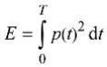 | N/A | |
| 3.3.19.4 | sound exposure level, SEL logarithmic measure of sound exposure relative to a reference value, E0 , typically the 1 kHz threshold of hearing in humans. Note 1 to entry: SEL is measured as A-weighted levels in dB. dB Note 2 to entry: See B.4 of EN 50332-3:2017 for additional information. | N/A | |
| 3.3.19.5 | digital signal level relative to full scale, dBFS levels reported in dBFS are always r. m.s. Full scale level, 0 dBFS, is the level of a dc-free 997-Hz sine wave whose undithered positive peak value is positive digital full scale, leaving the code corresponding to negative digital full scale unused Note 1 to entry: It is invalid to use dBFS for non-r. m.s. levels. Because the definition of full scale is based on a sine wave, the level of signals with a crest factor lower than that of a sine wave may exceed 0 dBFS. In particular, square wave signals may reach +3,01 dBFS. | N/A | |
| 2 | Modification to Clause 10 |
| IEC 62368-1 | |||
|---|---|---|---|
| Clause | Requirement-Test | Result-Remark | Verdict |
| 10.6 | Safeguards against acoustic energy sources Replace 10.6 of IEC 62368-1 with the following: | N/A | |
|---|---|---|---|
| 10.6.1.1 | Introduction Safeguard requirements for protection against long-term exposure to excessive sound pressure levels from personal music players closely coupled to the ear are specified below. Requirements for earphones and headphones intended for use with personal music players are also covered. A personal music player is a portable equipment intended for use by an ordinary person , that: – is designed to allow the user to listen to audio or audiovisual content / material; and – uses a listening device, such as headphones or earphones that can be worn in or on or around the ears; and – has a player that can be body worn (of a size suitable to be carried in a clothing pocket) and is intended for the user to walk around with while in continuous use (for example, on a street, in a subway, at an airport, etc. ) . EXAMPLES Portable CD players, MP3 audio players, mobile phones with MP3 type features, PDAs or similar equipment. Personal music players shall comply with the requirements of either 10.6.2 or 10.6.3. NOTE 1 Protection against acoustic energy sources from telecom applications is referenced to ITU-T P.360. NOTE 2 It is the intention of the Committee to allow the alternative methods for now, but to only use the dose measurement method as given in 10.6.5 in future. Therefore, manufacturers are encouraged to implement 10.6.5 as soon as possible. Listening devices sold separately shall comply with the requirements of 10.6.6. | N/A |
| IEC 62368-1 | |||
|---|---|---|---|
| Clause | Requirement-Test | Result-Remark | Verdict |
| These requirements are valid for music or video mode only. The requirements do not apply to: – professional equipment; NOTE 3 Professional equipment is equipment sold through special sales channels. All products sold through normal electronics stores are considered not to be professional equipment. – hearing aid equipment and other devices for assistive listening; – the following type of analogue personal music players: • long distance radio receiver (for example, amultiband radio receiver or world band radio receiver, an AM radio receiver), and • cassette player/recorder; NOTE 4 This exemption has been allowed because this technology is falling out of use and it is expected that within a few years it will no longer exist. This exemption will not be extended to other technologies. – a player while connected to an external amplifier that does not allow the user to walk around while in use. For equipment that is clearly designed or intended primarily for use by children, the limits of the relevant toy standards may apply. The relevant requirements are given in EN 71-1:2011, 4.20 and the related tests methods and measurement distances apply. | |||
|---|---|---|---|
| 10.6.1.2 | Non-ionizing radiation from radio frequencies in the range 0 to 300 GHz The amount of non-ionizing radiation is regulated by European Council Recommendation 1999/519/EC of 12 July 1999 on the limitation of exposure of the general public to electromagnetic | N/A |
| IEC 62368-1 | |||
|---|---|---|---|
| Clause | Requirement-Test | Result-Remark | Verdict |
| fields (0 Hz to 300 GHz) . For intentional radiators, ICNIRP guidelines should be taken into account for Limiting Exposure to Time-Varying Electric, Magnetic, and Electromagnetic Fields (up to 300 GHz) . For hand-held and body mounted devices, attention is drawn to EN 50360 and EN 50566. | |||
|---|---|---|---|
| 10.6.2 | Classification of devices without the capacity to estimate sound dose | ||
| 10.6.2.1 | General This standard is transitioning from short-term based (30 s) requirements to long-term based (40 hour) requirements. These clauses remain in effect only for devices that do not comply with sound dose estimation as stipulated in EN 50332-3. For classifying the acoustic output LAeq , T , measurements are based on the A-weighted equivalent sound pressure level over a 30 s period. For music where the average sound pressure (long term LAeq, T) measured over the duration of the song is lower than the average produced by the programme simulation noise, measurements maybe done over the duration of the complete song. In this case, T becomes the duration of the song. NOTE Classical music, acoustic music and broadcast typically has an average sound pressure (long term LAeq, T) which is much lower than the average programme simulation noise. Therefore, if the player is capable to analyse the content and compare it with the programme simulation noise, the warning does not need to be given as long as the average sound pressure of the song does not exceed the required limit. For example, if the player is set with the programme simulation noise to 85 dB, but the average music level of the song is only 65 dB, there is no need to give a warning or ask an acknowledgement as long as the average sound level of the song is not above the basic limit of 85 dB. | N/A | |
| 10.6.2.2 | RS1 limits (to be superseded, see 10.6.3.2) | N/A |
| IEC 62368-1 | |||
|---|---|---|---|
| Clause | Requirement-Test | Result-Remark | Verdict |
| RS1 is a class 1 acoustic energy source that does not exceed the following: – for equipment provided as a package (player with its listening device), and with a proprietary connector between the player and its listening device, or where the combination of player and listening device is known by other means such as setting or automatic detection, the LAeq, T acoustic output shall be ≤ 85 dB when playing the fixed“programme simulation noise” described in EN 50332-1. – for equipment provided with a standardized connector (for example, a 3,5 phone jack) that allows connection to a listening device for general use, the unweighted r. m.s. output voltage shall be ≤ 27 mV (analogue interface) or -25 dBFS (digital interface) when playing the fixed “programme simulation noise” described in EN 50332-1. – The RS1 limits will be updated for all devices as per 10.6.3.2. | |||
|---|---|---|---|
| 10.6.2.3 | RS2 limits (to be superseded, see 10.6.3.3) RS2 is a class 2 acoustic energy source that does not exceed the following: – for equipment provided as a package (player with its listening device), and with a proprietary connector between the player and its listening device, or when the combination of player and listening device is known by other means such as setting or automatic 130 detection, the LAeq, T acoustic output shall be ≤ 100 dB(A) when playing the fixed “programme simulation noise” as described in EN 50332-1. – for equipment provided with a standardized connector (for example, a 3,5 phone jack) that allows connection to a listening device for general use, the unweighted r. m.s. output voltage shall be ≤ 150 mV (analogue interface) or -10 dBFS (digital interface) when playing the fixed “programme simulation noise” as described in EN 50332-1. | N/A | |
| 10.6.2.4 | RS3 limits | N/A |
| IEC 62368-1 | |||
|---|---|---|---|
| Clause | Requirement-Test | Result-Remark | Verdict |
| RS3 is a class 3 acoustic energy source that exceeds RS2 limits. | |||
|---|---|---|---|
| 10.6.3 | Classification of devices (new) | N/A | |
| 10.6.3.1 | General Previous limits (10 .6.2) created abundant false negative and false positive PMP sound level warnings. New limits, compliant with The Commission Decision of 23 June 2009, are given below. | N/A | |
| 10.6.3.2 | RS1 limits (new) RS1 is a class 1 acoustic energy source that does not exceed the following: – for equipment provided as a package (player with its listening device), and with a proprietary connector between the player and its listening device, or where the combination of player and listening device is known by other means such as setting or automatic detection, the LAeq, T acoustic output shall be ≤ 80 dB when playing the fixed“programme simulation noise” described in EN 50332-1. – for equipment provided with a standardized connector (for example, a 3,5 phone jack) that allows connection to a listening device for general use, the unweighted r. m.s. output voltage shall be ≤ 15 mV (analogue interface) or -30 dBFS (digital interface) when playing the fixed “programme simulation noise” described in EN 50332-1. | N/A | |
| 10.6.3.3 | RS2 limits (new) RS2 is a class 2 acoustic energy source that does not exceed the following: – for equipment provided as a package (player with its listening device), and with a proprietary connector between the player and its listening device, or where the combination of player and listening device is known by other means such as setting or automatic detection, the weekly sound | N/A |
| IEC 62368-1 | |||
|---|---|---|---|
| Clause | Requirement-Test | Result-Remark | Verdict |
| exposure level, as described in EN 50332-3, shall be ≤ 80 dB when playing the fixed "programme simulation noise" described in EN 50332-1. – for equipment provided with a standardized connector (for example, a 3,5 phone jack) that allows connection to a listening device for general use, the unweighted r.m.s. output level, integrated over one week, as described in EN50332-3, shall be ≤ 15 mV (analogue interface) or -30 dBFS (digital interface) when playing the fixed“programme simulation noise” described in EN 50332-1. | |||
|---|---|---|---|
| 10.6.4 | Requirements for maximum sound exposure | N/A | |
| 10.6.4.1 | Measurement methods All volume controls shall be turned to maximum during tests. Measurements shall be made in accordance with EN 50332-1 or EN 50332-2 as applicable. | N/A | |
| 10.6.4.2 | Protection of persons Except as given below, protection requirements for parts accessible to ordinary persons , instructed persons and skilled persons are given in 4.3. NOTE 1 Volume control is not considered a safeguard. Between RS2 and an ordinary person , the basic safeguard may be replaced by an instructional safeguard in accordance with Clause F.5, except that the instructional safeguard shall be placedon the equipment, or on the packaging, or in the instruction manual. Alternatively, the instructional safeguard may be given through the equipment display during use. The elements of the instructional safeguard shall be as follows: – element 1a: the symbol , IEC 60417-6044 | N/A |
| IEC 62368-1 | |||
|---|---|---|---|
| Clause | Requirement-Test | Result-Remark | Verdict |
| (2011-01) – element 2: “High sound pressure” or equivalent wording – element 3: “Hearing damage risk” or equivalent wording – element 4: “Do not listen at high volume levels for long periods.” or equivalent wording An equipment safeguard shall prevent exposure of an ordinary person to an RS2 source without intentional physical action from the ordinary person and shall automatically return to an output level not exceeding what is specified for an RS1 source when the power is switched off. The equipment shall provide a means to actively inform the user of the increased sound level when the equipment is operated with an output exceeding RS1 . Any means used shall be acknowledged by the user before activating a mode of operation which allows for an output exceeding RS1 . The acknowledgement does not need to be repeated more than once every 20 h of cumulative listening time. NOTE 2 Examples of means include visual or audible signals. Action from the user is always needed. NOTE 3 The 20 h listening time is the accumulative listening time, independent of how often and how long the personal music player has been switched off. A skilled person shall not be unintentionally exposed to RS3 . | |||
|---|---|---|---|
| 10.6.5 | Requirements for dose.based systems | N/A | |
| 10.6.5.1 | General requirements Personal music players shall give the warnings as provided below when tested according to EN 50332-3, using the limits from this clause. | N/A |
| IEC 62368-1 | |||
|---|---|---|---|
| Clause | Requirement-Test | Result-Remark | Verdict |
| The manufacturer may offer optional settings to allow the users to modify when and how they wish to receive the notifications and warnings to promote a better user experience without defeating the safeguards. This allows the users to be informed ina method that best meets their physical capabilities and device usage needs. If such optional settings are offered, an administrator (for example, parental restrictions, business/educational administrators, etc. ) shall be able to lock any optional settings into a specific configuration. The personal music player shall be supplied with easy to understand explanation to the user of the dose management system, the risks involved, and how to use the system safely. The user shall be made aware that other sources may significantly contribute to their sound exposure, for example work, transportation, concerts, clubs, cinema, car races, etc. | |||
|---|---|---|---|
| 10.6.5.2 | Dose-based warning and requirements When a dose of 100 % CSD is reached, and at least at every 100 % further increase of CSD, the device shall warn the user and require an acknowledgement. In case the user does not acknowledge, the output level shall automatically decrease to compliance with class RS1 . The warning shall at least clearly indicate that listening above 100 % CSD leads to the risk of hearing damage or loss. | N/A | |
| 10.6.5.3 | Exposure-based requirements With only dose-based requirements, cause and effect could be far separated in time, defying the purpose of educating users about safe listening practice. In addition to dose-based requirements, a PMP shall therefore also put a limit to the short-term sound level a user can listen at. The exposure-based limiter (EL) shall automatically | N/A |
| IEC 62368-1 | |||
|---|---|---|---|
| Clause | Requirement-Test | Result-Remark | Verdict |
| reduce the sound level not to exceed 100 dB(A) or 150 mV integrated over the past 180 s, based on methodology defined in EN 50332-3. The EL settling time (time from starting level reduction to reaching target output) shall be 10 s or faster. Test of EL functionality is conducted according to EN 50332-3, using the limits from this clause. For equipment provided as a package (player with its listening device), the level integrated over 180 s shall be 100 dB or lower. For equipment provided with a standardized connector, the unweighted level integrated over 180 s shall be no more than 150 mV for an analogue interface and no more than -10 dBFS for a digital interface. NOTE In case the source is known not to be music (or test signal), the EL may be disabled. |
|---|
| 10.6.6 | Requirements for listening devices (headphones, earphones, etc.) | N/A | |
|---|---|---|---|
| 10.6.6.1 | Corded listening devices with analogue input With 94 dB LAeq acoustic pressure output of the listening device, and with the volume and sound settings in the listening device (for example, built-in volume level control, additional sound features like equalization, etc. ) set to the combination of positions that maximize the measured acoustic output, the input voltage of the listening device when playing the fixed “programme simulation noise” as described in EN 50332-1 shall be ≥ 75 mV. NOTE The values of 94 dB and 75 mV correspond with 85 dBand 27 mV or 100 dB and 150 mV. | N/A | |
| 10.6.6.2 | Corded listening devices with digital input With any playing device playing the fixed“programme simulation noise” described in EN 50332-1, and with the volume and sound settings in | N/A |
| IEC 62368-1 | |||
|---|---|---|---|
| Clause | Requirement-Test | Result-Remark | Verdict |
| the listening device (for example, built-in volume level control, additional sound features like equalization, etc. ) set to the combination of positions that maximize the measured acoustic output, the LAeq, T acoustic output of the listening device shall be ≤ 100 dB with an input signal of-10 dBFS. | |||
|---|---|---|---|
| 10.6.6.3 | Cordless listening devices In cordless mode, – with any playing and transmitting device playing the fixed programme simulation noise described in EN 50332-1; and – respecting the cordless transmission standards, where an air interface standard exists that specifies the equivalent acoustic level; and – with volume and sound settings in the receiving device (for example, built-in volume level control, additional sound features like equalization, etc. ) set to the combination of positions that maximize the measured acoustic output for the above mentioned programme simulation noise, the LAeq, T acoustic output of the listening device shall be ≤ 100 dB with an input signal of-10 dBFS. | N/A | |
| 10.6.6.4 | Measurement method Measurements shall be made in accordance with EN 50332-2 as applicable. | N/A | |
| 3 | Modification to the whole document | ||
| Delete all the “country” notes in the reference document according to the following list: | P |
| IEC 62368-1 | |||
|---|---|---|---|
| Clause | Requirement-Test | Result-Remark | Verdict |
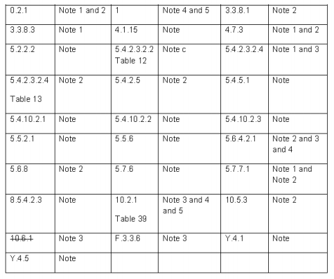 | ||||
|---|---|---|---|---|
| 4 | Modification to Clause 1 | P | ||
| 1 | Add the following note: NOTE Z1 The use of certain substances in electrical and electronic equipment is restricted within the EU: see Directive 2011/65/EU. | P | ||
| 5 | Modification to 4.Z1 | |||
| 4.Z1 | Add the following new subclause after 4. 9: To protect against excessive current, short-circuitsand earth faults in circuits connected to an a.c. mains, protective devices shall be included either as integral parts of the equipment or as parts of the building installation, subject to the following, a), b) and c): a) except as detailed in b) and c), protective devices necessary to comply with the requirements of B.3.1 and B.4 shall be included as parts of the equipment; b) for components in series with the mains input to the equipment such as the supply cord, appliance | N/A |
| IEC 62368-1 | |||
|---|---|---|---|
| Clause | Requirement-Test | Result-Remark | Verdict |
| coupler, r.f. i. filter and switch, short-circuit and earth fault protection may be provided by protective devices in the building installation; c) it is permitted for pluggable equipment type Bor permanently connected equipment , to rely on dedicated overcurrent and short-circuit protection in the building installation, provided that the means of protection, e.g. fuses or circuit breakers, is fully specified in the installation instructions. If reliance is placed on protection in the building installation, the installation instructions shall so state, except that for pluggable equipment type A the building installation shall be regarded as providing protection in accordance with the rating of the wall socket outlet. | ||||
|---|---|---|---|---|
| 6 | Modification to 5.4.2.3.2.4 | |||
| 5.4.2.3.2.4 | Add the following to the end of this subclause: The requirement for interconnection with external circuit is in addition given in EN 50491-3:2009 . | N/A | ||
| 7 | Modification to 10.2.1 | |||
| 10.2.1 | Add the following to c) and d) in table 39: For additional requirements, see 10.5.1. | N/A | ||
| 8 | Modification to 10.5.1 | |||
| 10.5.1 | Add the following after the first paragraph: For RS 1 compliance is checked by measurement under the following conditions: In addition to the normal operating conditions, all controls adjustable from the outside by hand, by any object such as a tool or a coin, and those internal adjustments or pre-sets which are not locked in a reliable manner, are adjusted so as to give maximum radiation whilst maintaining an intelligible picture for 1 h, at the end of which the measurement is made. | N/A |
| IEC 62368-1 | |||
|---|---|---|---|
| Clause | Requirement-Test | Result-Remark | Verdict |
| NOTE Z1 Soldered joints and paint lockings are examples of adequate locking. The dose-rate is determined by means of a radiation monitor with an effective area of 10 cm², at any point 10 cm from the outer surface of the apparatus. Moreover, the measurement shall be made under fault conditions causing an increase of the high voltage, provided an intelligible picture is maintained for 1 h, at the end of which the measurement is made. For RS1, the dose-rate shall not exceed 1 μSv/h taking account of the background level. NOTE Z2 These values appear in Directive 96/29/Euratom of 13 May 1996. | |||
|---|---|---|---|
| 9 | Modification to G.7.1 | ||
| G.7.1 | Add the following note: NOTE Z1 The harmonized code designations corresponding to the IEC cord types are given in Annex ZD. | N/A |
| 10 | Modification to Bibliography | |
|---|---|---|
| Add the following notes for the standards indicated: | P |
| IEC 62368-1 | |||
|---|---|---|---|
| Clause | Requirement-Test | Result-Remark | Verdict |
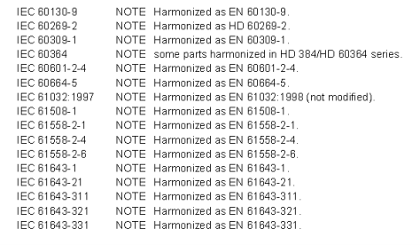 | |||
|---|---|---|---|
| 11 | ADDITION OF ANNEXES | ||
| ZB | ANNEX ZB, SPECIAL NATIONAL CONDITIONS (EN) | P | |
| 4.1.15 | Denmark, Finland, Norway and Sweden To the end of the subclause the following is added: Class I pluggable equipment type A intended for connection to other equipment or a network shall, if safety relies on connection to reliable earthing or if surge suppressors are connected between the network terminalsand accessible parts, have a marking stating that the equipment shall be connected to an earthed mains socket-outlet. The marking text in the applicable countries shall be as follows: In Denmark: “Apparatets stikprop skal tilsluttesen stikkontakt med jord som giver forbindelse til stikproppens jord.” In Finland: "Laite on liitettävä suojakoskettimilla varustettuun pistorasiaan" In Norway: “Apparatet må tilkoples jordetstikkontakt” In Sweden: “Apparaten skall anslutas till jordat uttag” | N/A |
| IEC 62368-1 | |||
|---|---|---|---|
| Clause | Requirement-Test | Result-Remark | Verdict |
| 4.7.3 | United Kingdom To the end of the subclause the following is added: The torque test is performed using a socket-outlet complying with BS 1363, and the plug part shall be assessed to the relevant clauses of BS 1363. Also see Annex G.4.2 of this annex | N/A | |
|---|---|---|---|
| 5.2.2.2 | Denmark After the 2nd paragraph add the following: A warning (marking safeguard) for high touch current is required if the touch current exceeds the limits of 3,5 mA a.c. or 10 mA d.c. | N/A | |
| 5.4.11.1and Annex G | Finland and Sweden To the end of the subclause the following is added: For separation of the telecommunication network from earth the following is applicable: If this insulation is solid, including insulation forming part of a component, it shall at least consist of either • two layers of thin sheet material, each of which shall pass the electric strength test below, or • one layer having a distance through insulation of at least 0,4 mm, which shall pass the electric strength test below. If this insulation forms part of a semiconductor component ([e.g. an](e.g. an) optocoupler), there is no distance through insulation requirement for the insulation consisting of an insulating compound completely filling the casing, so that clearancesand creepage distances do not exist, if the | N/A |
| IEC 62368-1 | |||
|---|---|---|---|
| Clause | Requirement-Test | Result-Remark | Verdict |
| component passes the electric strength test in accordance with the compliance clause below and in addition • passes the tests and inspection criteria of 5.4.8 with an electric strength test of 1,5 kV multiplied by 1,6 (the electric strength test of 5.4.9 shall be performed using 1,5 kV), and • is subject to routine testing for electric strength during manufacturing, using a test voltage of 1,5 kV. It is permitted to bridge this insulation with a capacitor complying with EN 60384-14:2005, subclass Y2 . A capacitor classified Y3 according to EN 60384-14:2005, may bridge this insulation under the following conditions: • the insulation requirements are satisfied by having a capacitor classified Y3 as defined by EN 60384-14, which in addition to the Y3 testing, is tested with an impulse test of 2,5 kV defined in 5.4. 11; • the additional testing shall be performed on all the test specimens as described in EN 60384-14; the impulse test of 2,5 kV is to be performed before the endurance test in EN 60384-14, in the sequence of tests as described in EN 60384-14. | |||
|---|---|---|---|
| 5.5.2.1 | Norway After the 3rd paragraph the following is added: Due to the IT power system used, capacitors are required to be rated for the applicable line-to-line | N/A |
| IEC 62368-1 | |||
|---|---|---|---|
| Clause | Requirement-Test | Result-Remark | Verdict |
| voltage (230 V) . | |||
|---|---|---|---|
| 5.5.6 | Finland, Norway and Sweden To the end of the subclause the following is added: Resistors used as basic safeguard or bridging basic insulation in class I pluggable equipment type A shall comply with G.10.1 and the test of G.10.2. | N/A | |
| 5.6.1 | Denmark Add to the end of the subclause Due to many existing installations where the socket-outlets can be protected with fuses with higher rating than the rating of the socket-outlets the protection for pluggable equipment type A shall be an integral part of the equipment. Justification: In Denmark an existing 13 A socket outlet can be protected by a 20 A fuse. | N/A | |
| 5.6.4.2.1 | Ireland and United Kingdom After the indent for pluggable equipment type A, the following is added: – the protective current rating is taken to be 13 A, this being the largest rating of fuse used in the mains plug. | N/A | |
| 5.6.4.2.1 | France After the indent for pluggable equipment type A, the following is added: – in certain cases, the protective current rating of the circuit supplied from the mains is taken as 20 A instead of 16 A. | N/A | |
| 5.6.5.1 | To the second paragraph the following is added: The range of conductor sizes of flexible cords tobe accepted by terminals for equipment with a rated current over 10 A and up to and including | N/A |
| IEC 62368-1 | |||
|---|---|---|---|
| Clause | Requirement-Test | Result-Remark | Verdict |
| 13 A is: 1,25 mm2 to 1,5 mm2 in cross-sectional area. | |||
|---|---|---|---|
| 5.6.8 | Norway To the end of the subclause the following is added: Equipment connected with an earthed mains plug is classified as class I equipment. See the Norway marking requirement in 4.1.15. The symbol IEC 60417-6092, as specified in F.3.6.2, is accepted. | N/A | |
| 5.7.6 | Denmark To the end of the subclause the following is added: The installation instruction shall be affixed to the equipment if the protective conductor current exceeds the limits of 3,5 mA a.c. or 10 mA d.c. | N/A | |
| 5.7.6.2 | Denmark To the end of the subclause the following is added: The warning (marking safeguard) for high touch current is required if the touch current or the protective current exceed the limits of 3,5 mA . | N/A | |
| 5.7.7.1 | Norway and Sweden To the end of the subclause the following is added: The screen of the television distribution system is normally not earthed at the entrance of the building and there is normally no equipotential bonding system within the building. Therefore the protective earthing of the building installation needs to be isolated from the screen of a cable distribution system. It is however accepted to provide the insulation external to the equipment by an adapter or an interconnection cable with galvanic isolator, which may be provided by a retailer, for example. | N/A |
| IEC 62368-1 | |||
|---|---|---|---|
| Clause | Requirement-Test | Result-Remark | Verdict |
| The user manual shall then have the following or similar information in Norwegian and Swedish language respectively, depending on in what country the equipment is intended to be used in: “Apparatus connected to the protective earthing of the building installation through the mains connection or through other apparatus with a connection to protective earthing – and to a television distribution system using coaxial cable, may in some circumstances create a fire hazard. Connection to a television distribution system therefore has to be provided through a device providing electrical isolation below a certain frequency range (galvanic isolator, see EN 60728-11)” NOTE In Norway, due to regulation for CATV-installations, and in Sweden, a galvanic isolator shall provide electrical insulation below 5 MHz. The insulation shall withstand adielectric strength of 1,5 kV r. m.s. , 50 Hz or 60 Hz, for 1 min. Translation to Norwegian (the Swedish text will also be accepted in Norway): “Apparater som er koplet til beskyttelsesjord via nettplugg og/eller via annet jordtilkoplet utstyr – og er tilkoplet et koaksialbasert kabel-TV nett, kan forårsake brannfare. For å unngå dette skal det ved tilkopling avapparater til kabel-TV nett installeres en galvanisk isolator mellom apparatet og kabel-TV nettet.” Translation to Swedish: ”Apparater som är kopplad till skyddsjord via jordat vägguttag och/eller via annan utrustning och samtidigt är kopplad till kabel-TV nät kan ivissa fall medfőra risk főr brand. Főr att undvikadetta skall vid anslutning av apparaten till kabel-TV nät galvanisk isolator finnas mellan |
|---|
| IEC 62368-1 | |||
|---|---|---|---|
| Clause | Requirement-Test | Result-Remark | Verdict |
| apparaten och kabel-TV nätet.”. | |||
|---|---|---|---|
| 8.5.4.2.3 | United Kingdom Add the following after the 2nd dash bullet in 3rd paragraph: An emergency stop system complying with the requirements of IEC 60204-1 and ISO 13850 is required where there is a risk of personal injury. | N/A | |
| B.3.1 and B.4 | Ireland and United Kingdom The following is applicable: To protect against excessive currents and short-circuits in the primary circuit of direct plug-in equipment , tests according to Annexes B.3.1 and B.4 shall be conducted using an external miniature circuit breaker complying with EN 60898-1, Type B, rated 32A. If the equipment does not pass these tests, suitable protective devices shall be included as an integral part of the direct plug-in equipment , until the requirements of Annexes B.3.1 and B.4 are met | N/A | |
| G.4.2 | Denmark To the end of the subclause the following is added: Supply cords of single phase appliances having a rated current not exceeding 13 A shall be provided with a plug according to DS 60884-2-D1:2011 . CLASS I EQUIPMENT provided with socket-outlets with earth contacts or which are intended to be used in locations where protection against indirect contact is required according to the wiring rules shall be provided with a plug in accordance with standard sheet DK 2-1a or DK 2-5a. If a single-phase equipment having a RATED | N/A |
| IEC 62368-1 | |||
|---|---|---|---|
| Clause | Requirement-Test | Result-Remark | Verdict |
| CURRENT exceeding 13 A or if a polyphase equipment is provided with a supply cord with a plug, this plug shall be in accordance with the standard sheets DK 6-1a in DS 60884-2-D1 or EN 60309-2. Mains socket outlets intended for providing power to Class II apparatus with a rated current of 2,5 A shall be in accordance DS 60884-2-D1:2011 standard sheet DKA 1-4a. Other current rating socket outlets shall be in compliance with Standard Sheet DKA 1-3a or DKA 1-1c. Mains socket-outlets with earth shall be in compliance with DS 60884-2-D1:2011 Standard Sheet DK 1-3a, DK 1-1c, DK1-1d, DK 1-5a or DK 1-7a Justification: Heavy Current Regulations, Section 6c | |||
|---|---|---|---|
| G.4.2 | United Kingdom To the end of the subclause the following is added: The plug part of direct plug-in equipment shall be assessed to BS 1363: Part 1, 12. 1, 12.2, 12.3, 12.9, 12. 11, 12. 12, 12. 13, 12. 16, and 12. 17, except that the test of 12.17 is performed at not less than 125 °C. Where the metal earth pin is replaced by an Insulated Shutter Opening Device (ISOD), the requirements of clauses 22.2 and 23 also apply. | N/A | |
| G.7.1 | United Kingdom To the first paragraph the following is added: Equipment which is fitted with a flexible cable or cord and is designed to be connected to a mains | N/A |
| IEC 62368-1 | |||
|---|---|---|---|
| Clause | Requirement-Test | Result-Remark | Verdict |
| socket conforming to BS 1363 by means of that flexible cable or cord shall be fitted with a‘standard plug’ in accordance with the Plugs and Sockets etc. (Safety) Regulations 1994, Statutory Instrument 1994 No. 1768, unless exempted by those regulations. NOTE "Standard plug" is defined in SI 1768:1994 and essentially means an approved plug conforming to BS 1363 or an approved conversion plug. | |||
|---|---|---|---|
| G.7.1 | Ireland To the first paragraph the following is added: Apparatus which is fitted with a flexible cable or cord shall be provided with a plug in accordance with Statutory Instrument 525: 1997,“13 A Plugsand Conversion Adapters for Domestic Use Regulations: 1997. S. I. 525 provides for the recognition of a standard of another Member State which is equivalent to the relevant Irish Standard | N/A | |
| G.7.2 | Ireland and United Kingdom To the first paragraph the following is added: A power supply cord with a conductor of 1,25 mm2 is allowed for equipment which is rated over 10 A and up to and including 13 A. | N/A | |
| ZC | ANNEX ZC, NATIONAL DEVIATIONS (EN) | ||
| 10.5.2 | Germany The following requirement applies: For the operation of any cathode ray tube intended for the display of visual images operating at an acceleration voltage exceeding 40 kV, authorization is required, or application of type approval (Bauartzulassung) and marking. | N/A |
| IEC 62368-1 | |||
|---|---|---|---|
| Clause | Requirement-Test | Result-Remark | Verdict |
| Justification: German ministerial decree against ionizing radiation (Röntgenverordnung), in force since 2002-07-01, implementing the European Directive 96/29/EURATOM. NOTE Contact address: Physikalisch-Technische Bundesanstalt, Bundesallee 100, D-38116 Braunschweig, Tel.: Int+49-531-592-6320, Internet: http://www.ptb.de | |||
|---|---|---|---|
| ZD | IEC and CENELEC CODE DESIGNATIONS FOR FLEXIBLE CORDS (EN) | ||
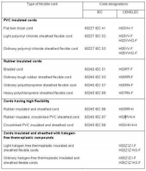 | N/A |
| IEC 62368-1 | |||
|---|---|---|---|
| Clause | Requirement-Test | Result-Remark | Verdict |
| 5.2 | TABLE: Classification of electrical energy sources | P | |||||||
|---|---|---|---|---|---|---|---|---|---|
| Supply Voltage | Location (e.g. circuit designation) | Test conditions | Parameters | ES Class | |||||
| U (V) | I (mA) | Type1) | Additional Info 2) | ||||||
| 5.5Vd.c. | Input circuit | Normal | 5.5Vd.c. | -- | -- | -- | ES1 | ||
| Supplementary information: | |||||||||
| 1) Type: Steady state (SS), Capacitance (CP), Single pulse (SP), Repetitive pulses (RP), etc. 2) Additional Info: Frequency, Pulse duration, Pulse off time, Capacitance value, etc. |
| 5.4.1.8 | TABLE: Working voltage measurement | N/A | ||||
|---|---|---|---|---|---|---|
| Location | RMS voltage (V) | Peak voltage (V) | Frequency (Hz) | Comments | ||
| -- | -- | -- | -- | -- | ||
| -- | -- | -- | -- | -- | ||
| Supplementary information: | ||||||
| 5.4.1.10.2 | TABLE: Vicat softening temperature of thermoplastics | N/A | ||||
|---|---|---|---|---|---|---|
| Method................................................................ ....................... : | ISO 306 / B50 | _ | ||||
| Object/ Part No./Material | Manufacturer/trademark | Thickness (mm) | T softening (°C) | |||
| -- | -- | -- | -- | |||
| -- | -- | -- | -- | |||
| Supplementary information: | ||||||
| 5.4.1.10.3 | TABLE: Ball pressure test of thermoplastics | N/A | |||||
|---|---|---|---|---|---|---|---|
| Allowed impression diameter (mm) ................................ : | ≤ 2 mm | _ | |||||
| Object/Part No./Material | Manufacturer/trademark | Thickness (mm) | Test temperature (oC) | Impression diameter (mm) | |||
| -- | -- | -- | -- | -- | |||
| -- | -- | -- | -- | -- |
| IEC 62368-1 | |||
|---|---|---|---|
| Clause | Requirement-Test | Result-Remark | Verdict |
| Supplementary information: |
|---|
| 5.4.2, 5.4.3 | TABLE: Minimum Clearances/Creepage distance | N/A | ||||||||
|---|---|---|---|---|---|---|---|---|---|---|
| Clearance (cl) and creepage distance (cr) at/of/between: | Up (V) | Urms (V) | Freq 1)(Hz) | Required cl (mm) | cl (mm) | E.S. 2)(V) | Required cr (mm) | cr (mm) | ||
| -- | -- | -- | -- | -- | -- | -- | -- | -- | ||
| Supplementary information: | ||||||||||
| 1) Only for frequency above 30 kHz 2) Complete Electric Strength voltage (E.S. (V) when 5.4.2.4 applied) |
| 5.4.4.2 | TABLE: Minimum distance through insulation | N/A | ||||
|---|---|---|---|---|---|---|
| Distance through insulation (DTI) at/of | Peak voltage (V) | Insulation | Required DTI (mm) | Measured DTI (mm) | ||
| -- | -- | -- | -- | -- | ||
| Supplementary information: | ||||||
| 5.4.4.9 | TABLE: Solid insulation at frequencies >30 kHz | N/A | ||||||
|---|---|---|---|---|---|---|---|---|
| Insulation material | EP | Frequency (kHz) | ĸR | Thickness d (mm) | Insulation | VPW (Vpk) | ||
| -- | -- | -- | -- | -- | -- | -- | ||
| Supplementary information: | ||||||||
| 5.4.9 | TABLE: Electric strength tests | N/A | |||
|---|---|---|---|---|---|
| Test voltage applied between: | Voltage shape (Surge, Impulse, AC, DC, etc.) | Test voltage (V) | Breakdown Yes / No | ||
| -- | -- | -- | -- | ||
| -- | -- | -- | -- |
| IEC 62368-1 | |||
|---|---|---|---|
| Clause | Requirement-Test | Result-Remark | Verdict |
| Supplementary information: |
|---|
| 5.5.2.2 | TABLE: Stored discharge on capacitors | N/A | |||||
|---|---|---|---|---|---|---|---|
| Location | Supply voltage (V) | Operating and fault condition 1) | Switch position | Measured voltage (Vpk) | ES Class | ||
| -- | -- | -- | -- | -- | -- | ||
| Supplementary information: | |||||||
| X-capacitors installed for testing: [ ] bleeding resistor rating: [ ] ICX: 1) Normal operating condition (e.g. , normal operation, or open fuse), SC= short circuit, OC= open circuit |
| 5.6.6 | TABLE: Resistance of protective conductors and terminations | N/A | ||||
|---|---|---|---|---|---|---|
| Location | Test current (A) | Duration (min) | Voltage drop (V) | Resistance (Ω) | ||
| -- | -- | -- | -- | -- | ||
| Supplementary information: | ||||||
| 5.7.4 | TABLE: Unearthed accessible parts | N/A | ||||||
|---|---|---|---|---|---|---|---|---|
| Location | Operating and fault conditions | Supply Voltage (V) | Parameters | ES class | ||||
| Voltage (Vrms or Vpk) | Current (Arms or Apk) | Freq.(Hz) | ||||||
| -- | -- | -- | -- | -- | -- | -- | ||
| Supplementary information: | ||||||||
| Abbreviation: SC= short circuit; OC= open circuit |
| 5.7.5 | TABLE: Earthed accessible conductive part | N/A | |
|---|---|---|---|
| Supply voltage (V) .........................: | _ | ||
| Phase(s) ................................ : | [ ] Single Phase; [ ] Three Phase: [ ] Delta [ ] Wye | ||
| Power Distribution System ..........: | [ ] TN [ ]TT [ ] IT |
| IEC 62368-1 | |||
|---|---|---|---|
| Clause | Requirement-Test | Result-Remark | Verdict |
| Location | Fault Condition No in IEC 60990 clause 6.2.2 | Touch current (mA) | Comment |
|---|---|---|---|
| -- | -- | -- | -- |
| Supplementary Information: | |||
| 5.8 | TABLE: Backfeed safeguard in battery backed up supplies | N/A | ||||||
|---|---|---|---|---|---|---|---|---|
| Location | Supply voltage (V) | Operating and fault condition | Time (s) | Open-circuit voltage (V) | Touch current (A) | ES Class | ||
| -- | -- | -- | -- | -- | -- | -- | ||
| Supplementary information: | ||||||||
| Abbreviation: SC= short circuit, OC= open circuit |
| 6.2.2 | TABLE: Power source circuit classifications (Model: AC981A) | P | ||||||
|---|---|---|---|---|---|---|---|---|
| Location | Operating and fault condition | Voltage (V) | Current (A) | Max. Power1) (W) | Time (S) | PS class | ||
| Input circuit | Normal condition | -- | -- | -- | -- | PS3* | ||
| lnput VPWR: 4.5-5,5 Vd.c. | ||||||||
| VBAT | Max load | 4.10 | 0.289 | 1.19 | 3 | PS1 | ||
| VOUT0 | Max load | 4.86 | 0.093 | 0.452 | 3 | PS1 | ||
| VOUT1 | Max load | 4.87 | 0.093 | 0.453 | 3 | PS1 | ||
| lnput VBAT:3-4 .5Vd.c. | ||||||||
| VOUT0 | Max load | 4.85 | 0.093 | 0.452 | 3 | PS1 | ||
| VOUT1 | Max load | 4.86 | 0.093 | 0.452 | 3 | PS1 | ||
| Supplementary information: | ||||||||
| Abbreviation: SC= short circuit; OC= open circuit 1) Measured after 3 s for PS1 and measured after 5 s for PS2 and PS3 . *The input power for the lC is from external power source, PS3 was assumed. |
| IEC 62368-1 | |||
|---|---|---|---|
| Clause | Requirement-Test | Result-Remark | Verdict |
| 6.2.2 | TABLE: Power source circuit classifications (Model: AC982A) | P | ||||||
|---|---|---|---|---|---|---|---|---|
| Location | Operating and fault condition | Voltage (V) | Current (A) | Max. Power1) (W) | Time (S) | PS class | ||
| Input circuit | Normal condition | -- | -- | -- | -- | PS3* | ||
| lnput VPWR: 4.5-5,5 Vd.c. | ||||||||
| VBAT | Max load | 4.09 | 0.292 | 1.20 | 3 | PS1 | ||
| VOUT0 | Max load | 4.82 | 0.092 | 0.444 | 3 | PS1 | ||
| VOUT1 | Max load | 4.82 | 0.096 | 0.463 | 3 | PS1 | ||
| lnput VBAT:3-4 .5Vd.c. | ||||||||
| VOUT0 | Max load | 4.80 | 0.092 | 0.442 | 3 | PS1 | ||
| VOUT1 | Max load | 4.81 | 0.095 | 0.457 | 3 | PS1 | ||
| Supplementary information: | ||||||||
| Abbreviation: SC= short circuit; OC= open circuit 2) Measured after 3 s for PS1 and measured after 5 s for PS2 and PS3 . *The input power for the lC is from external power source, PS3 was assumed. |
| 6.2.3.1 | TABLE: Determination of Arcing PIS | N/A | ||||
|---|---|---|---|---|---|---|
| Location | Open circuit voltage after 3 s (Vpk) | Measured r. m.s current (A) | Calculated value | Arcing PIS? Yes / No | ||
| See below | -- | -- | -- | -- | ||
| Supplementary information: | ||||||
| 6.2.3.2 | TABLE: Determination of resistive PIS | P | |||
|---|---|---|---|---|---|
| Location | Operating and fault condition | Dissipate power (W) | Arcing PIS? Yes / No | ||
| Internal part/ component | -- | -- | Yes (declared) | ||
| Supplementary information: | |||||
| Abbreviation: SC= short circuit; OC= open circuit |
| IEC 62368-1 | |||
|---|---|---|---|
| Clause | Requirement-Test | Result-Remark | Verdict |
| 8.5.5 | TABLE: High pressure lamp | N/A | ||||
|---|---|---|---|---|---|---|
| Lamp manufacturer | Lamp type | Explosion method | Longest axis of glass particle (mm) | Particle found beyond 1 m Yes / No | ||
| Supplementary information: | ||||||
| 9.6 | TABLE: Temperature measurements for wireless power transmitters | N/A | |||||||||
|---|---|---|---|---|---|---|---|---|---|---|---|
| Supply voltage (V) ................................ : | _ | ||||||||||
| Max. transmit power of transmitter (W) : | _ | ||||||||||
| Foreign objects | w/o receiver and direct contact | with receiver and direct contact | with receiver and at distance of 2 mm | with receiver and at distance of 5 mm | |||||||
| Object ( oC) | Ambient ( oC) | Object ( oC) | Ambient ( oC) | Object ( oC) | Ambient ( oC) | Object ( oC) | Ambient ( oC) | ||||
| Supplementary information: | |||||||||||
| 5.4.1.4, 9.3, B.1.5, B.2.6 | TABLE: Temperature measurements (Model: AC981A) | P | |||||
|---|---|---|---|---|---|---|---|
| Supply voltage (V) ................................ : | lnput VPWR: 4.5-5,5 Vd.c. | lnput VBAT: 3-4.5Vd.c. | _ | ||||
| Ambient temperature during test Tamb (oC) .: | See below | See below | See below | See below | _ | ||
| Maximum measured temperature T of part/at: | T (oC) | Allowed Tmax (oC) | |||||
| 4.40Vdc (output VBAT at 400mA) | |||||||
| lC body | 32.8 | 93.1 | -- | -- | -- | ||
| PCB near IC | 33.4 | 93.7 | -- | -- | 130 |
| IEC 62368-1 | |||
|---|---|---|---|
| Clause | Requirement-Test | Result-Remark | Verdict |
| Ambient | 24.7 | 85.0 | -- | -- | -- | |||||
|---|---|---|---|---|---|---|---|---|---|---|
| 5Vdc (output VOUT0 at 100mA) | ||||||||||
| lC body | 37.3 | 97.7 | 26.5 | 87.2 | -- | |||||
| PCB near IC | 38.2 | 98.6 | 26.6 | 87.3 | 130 | |||||
| Ambient | 24.6 | 85.0 | 24.3 | 85.0 | -- | |||||
| 5Vdc (output VOUT1 at 100mA) | ||||||||||
| lC body | 37.6 | 97.6 | 26.6 | 87.1 | -- | |||||
| PCB near IC | 38.9 | 98.9 | 26.5 | 87.0 | 130 | |||||
| Ambient | 25.0 | 85.0 | 24.5 | 85.0 | -- | |||||
| 5Vdc (output VOUT at 200mA) | ||||||||||
| lC body | 36.8 | 97.7 | 27.7 | 88.3 | -- | |||||
| PCB near IC | 38.1 | 99.0 | 27.8 | 88.4 | 130 | |||||
| Ambient | 24.1 | 85.0 | 24.4 | 85.0 | -- | |||||
| Temperature T of winding: | t1 (°C) | R 1 (Ω) | t2 (°C) | R2 (Ω) | T (oC) | Allowed Tmax (oC) | Insulation class | |||
| Supplementary information: | ||||||||||
| Supplementary information: * Temperature limit for TS1 of accessible enclosure according to Table 38. Note 1: Tma should be considered as directed by applicable requirement. Note 2: Tma is not included in assessment of Touch Temperatures (Clause 9) . Note 3: The maximum ambient temperature specified by manufacturer is 85oC. Note 4: All values for T(C) are re-calculated from Tamb respectively. |
| IEC 62368-1 | |||
|---|---|---|---|
| Clause | Requirement-Test | Result-Remark | Verdict |
| 5.4.1.4, 9.3, B.1.5, B.2.6 | TABLE: Temperature measurements (Model: AC982A) | P | ||||||||||
|---|---|---|---|---|---|---|---|---|---|---|---|---|
| Supply voltage (V) ................................ : | lnput VPWR: 4.5-5,5 Vd.c. | lnput VBAT: 3-4.5Vd.c. | _ | |||||||||
| Ambient temperature during test Tamb (oC) .: | See below | See below | See below | See below | _ | |||||||
| Maximum measured temperature T of part/at: | T (oC) | Allowed Tmax (oC) | ||||||||||
| 4.40Vdc (output VBAT at 400mA) | ||||||||||||
| lC body | 32.4 | 93.0 | -- | -- | -- | |||||||
| PCB near IC | 31.2 | 91.8 | -- | -- | 130 | |||||||
| Ambient | 24.4 | 85.0 | -- | -- | -- | |||||||
| 5Vdc (output VOUT0 at 100mA) | ||||||||||||
| lC body | 35.9 | 96.7 | 26.6 | 87.1 | -- | |||||||
| PCB near IC | 34.2 | 95.0 | 26.1 | 86.6 | 130 | |||||||
| Ambient | 24.2 | 85.0 | 24.5 | 85.0 | -- | |||||||
| 5Vdc (output VOUT1 at 100mA) | ||||||||||||
| lC body | 37.1 | 96.4 | 26.4 | 87.1 | -- | |||||||
| PCB near IC | 35.8 | 95.1 | 25.9 | 86.6 | 130 | |||||||
| Ambient | 25.7 | 85.0 | 24.3 | 85.0 | -- | |||||||
| 5Vdc (output VOUT at 200mA) | ||||||||||||
| lC body | 37.8 | 97.5 | 28.3 | 88.2 | -- | |||||||
| PCB near IC | 35.8 | 95.5 | 27.8 | 87.7 | 130 | |||||||
| Ambient | 25.3 | 85.0 | 25.1 | 85.0 | -- | |||||||
| Temperature T of winding: | t1 (°C) | R 1 (Ω) | t2 (°C) | R2 (Ω) | T (oC) | Allowed Tmax (oC) | Insulation class | |||||
| Supplementary information: | ||||||||||||
| Supplementary information: * Temperature limit for TS1 of accessible enclosure according to Table 38. Note 1: Tma should be considered as directed by applicable requirement. Note 2: Tma is not included in assessment of Touch Temperatures (Clause 9) . |
| IEC 62368-1 | |||
|---|---|---|---|
| Clause | Requirement-Test | Result-Remark | Verdict |
Note 3: The maximum ambient temperature specified by manufacturer is 85oC.
Note 4: All values for T(C) are re-calculated from Tamb respectively.
| B.2.5 | TABLE: Input test | N/A | ||||||||
|---|---|---|---|---|---|---|---|---|---|---|
| U (V) | Hz | I (A) | I rated (A) | P (W) | P rated (W) | Fuse No | I fuse (A) | Condition/status | ||
| Supplementary information: | ||||||||||
| B.3, B.4 | TABLE: Abnormal operating and fault condition tests (Model: AC981A) | P | |||||||
|---|---|---|---|---|---|---|---|---|---|
| Ambient temperature Tamb (oC) ................................ ................ : | See follow | _ | |||||||
| Power source for EUT: Manufacturer, model/type, outputrating : | -- | _ | |||||||
| Component No. | Condition | Supply voltage (V) | Test time | Fuse no. | Fuse current (A) | Observation | |||
| lnput VPWR: 4.5-5,5 Vd.c. | |||||||||
| Power Pin lN (Output: VBAT) | Annex G.9 test line 4 | 5.5VDC | 50 cycles | -- | -- | Power pin voltage: 5.5 Vdc to 0Vdc 50 cycles at 70oC VBAT: 4.20Vdc and 300mA. After test, VBAT output current limit function maintains. | |||
| Power Pin lN (Output: VBAT) | Annex G.9 test line 5 | 5.5VDC | 50 cycles | -- | -- | Power pin voltage: 5.5 Vdc to 0Vdc 50 cycles at-30oC VBAT: 4.20Vdc and 300mA. After test, VBAT output current limit function maintains. | |||
| Output (Output: VBAT) | Annex G.9 test line 6 | 5.5VDC | 50 cycles | -- | -- | BAT voltage: open to short 50 cycles After test, VBAT output current limit function maintains. | |||
| Power Pin lN (Output: VBAT) | Annex G.9 test line 8 | 5.5VDC | 50 cycles | -- | -- | Power pin voltage: 5.5 Vdc to 0Vdc 50 cycles VBAT: 4.20Vdc andoverloaded to 300mA After test, VBAT output current limit function maintains. |
| IEC 62368-1 | |||
|---|---|---|---|
| Clause | Requirement-Test | Result-Remark | Verdict |
| Power Pin lN (Output: VOUT0) | Annex G.9 test line 4 | 5.5VDC | 50 cycles | -- | -- | Power pin voltage: 5.5 Vdc to 0Vdc 50 cycles at 70oC VOUT0: 5Vdc and 100mA. After test, VBAT output current limit function maintains. |
|---|---|---|---|---|---|---|
| Power Pin lN (Output: VOUT0) | Annex G.9 test line 5 | 5.5VDC | 50 cycles | -- | -- | Power pin voltage: 5.5 Vdc to 0Vdc 50 cycles at-30oC VOUT0: 5Vdc and 100mA. After test, VBAT output current limit function maintains. |
| Output (Output: VOUT0) | Annex G.9 test line 6 | 5.5VDC | 50 cycles | -- | -- | BAT voltage: open to short 50 cycles After test, VBAT output current limit function maintains. |
| Power Pin lN (Output: VOUT0) | Annex G.9 test line 8 | 5.5VDC | 50 cycles | -- | -- | Power pin voltage: 5.5 Vdc to 0Vdc 50 cycles VOUT0: 5Vdc and overloaded to 100mA After test, VBAT output current limit function maintains. |
| Power Pin lN (Output: VOUT1) | Annex G.9 test line 4 | 5.5VDC | 50 cycles | -- | -- | Power pin voltage: 5.5 Vdc to 0Vdc 50 cycles at 70oC VOUT1: 5Vdc and 100mA. After test, VBAT output current limit function maintains. |
| Power Pin lN (Output: VOUT1) | Annex G.9 test line 5 | 5.5VDC | 50 cycles | -- | -- | Power pin voltage: 5.5 Vdc to 0Vdc 50 cycles at-30oC VOUT1: 5Vdc and 100mA. After test, VBAT output current limit function maintains. |
| Output (Output: VOUT1) | Annex G.9 test line 6 | 5.5VDC | 50 cycles | -- | -- | BAT voltage: open to short 50 cycles After test, VBAT output current limit function maintains. |
| Power Pin lN (Output: VOUT1) | Annex G.9 test line 8 | 5.5VDC | 50 cycles | -- | -- | Power pin voltage: 5.5 Vdc to 0Vdc 50 cycles VOUT1: 5Vdc and overloaded to100mA After test, VBAT output current limit function maintains. |
| lnput VBAT:3-4 .5Vd.c. |
| IEC 62368-1 | |||
|---|---|---|---|
| Clause | Requirement-Test | Result-Remark | Verdict |
| Power Pin lN (Output: VOUT0) | Annex G.9 test line 4 | 4.5VDC | 50 cycles | -- | -- | Power pin voltage: 4.5 Vdc to 0Vdc 50 cycles at 70oC VOUT0: 5Vdc and 100mA. After test, VBAT output current limit function maintains. |
|---|---|---|---|---|---|---|
| Power Pin lN (Output: VOUT0) | Annex G.9 test line 5 | 4.5VDC | 50 cycles | -- | -- | Power pin voltage: 4.5 Vdc to 0Vdc 50 cycles at-30oC VOUT0: 5Vdc and 100mA. After test, VBAT output current limit function maintains. |
| Output (Output: VOUT0) | Annex G.9 test line 6 | 4.5VDC | 50 cycles | -- | -- | BAT voltage: open to short 50 cycles After test, VBAT output current limit function maintains. |
| Power Pin lN (Output: VOUT0) | Annex G.9 test line 8 | 4.5VDC | 50 cycles | -- | -- | Power pin voltage: 4.5 Vdc to 0Vdc 50 cycles VOUT0: 5Vdc and overloaded to 100mA After test, VBAT output current limit function maintains. |
| Power Pin lN (Output: VOUT1) | Annex G.9 test line 4 | 4.5VDC | 50 cycles | -- | -- | Power pin voltage: 4.5 Vdc to 0Vdc 50 cycles at 70oC VOUT1: 5Vdc and 100mA. After test, VBAT output current limit function maintains. |
| Power Pin lN (Output: VOUT1) | Annex G.9 test line 5 | 4.5VDC | 50 cycles | -- | -- | Power pin voltage: 4.5 Vdc to 0Vdc 50 cycles at-30oC VOUT1: 5Vdc and 100mA. After test, VBAT output current limit function maintains. |
| Output (Output: VOUT1) | Annex G.9 test line 6 | 4.5VDC | 50 cycles | -- | -- | BAT voltage: open to short 50 cycles After test, VBAT output current limit function maintains. |
| Power Pin lN (Output: VOUT1) | Annex G.9 test line 8 | 4.5VDC | 50 cycles | -- | -- | Power pin voltage: 4.5 Vdc to 0Vdc 50 cycles VOUT1: 5Vdc and overloaded to 100mA After test, VBAT output current limit function maintains. |
| Supplementary information: |
| IEC 62368-1 | |||
|---|---|---|---|
| Clause | Requirement-Test | Result-Remark | Verdict |

| B.3, B.4 | TABLE: Abnormal operating and fault condition tests (Model: AC982A) | P | |||||||
|---|---|---|---|---|---|---|---|---|---|
| Ambient temperature Tamb (oC) ................................ ................ : | See follow | _ | |||||||
| Power source for EUT: Manufacturer, model/type, outputrating : | -- | _ | |||||||
| Component No. | Condition | Supply voltage (V) | Test time | Fuse no. | Fuse current (A) | Observation | |||
| lnput VPWR: 4.5-5,5 Vd.c. | |||||||||
| Power Pin lN (Output: VBAT) S02 | Annex G.9 test line 4 | 5.5VDC | 50 cycles | -- | -- | Power pin voltage: 5.5 Vdc to 0Vdc 50 cycles at 70oC VBAT: 4.20Vdc and 300mA. After test, VBAT output current limit function maintains. | |||
| Power Pin lN (Output: VBAT) | Annex G.9 test line 5 | 5.5VDC | 50 cycles | -- | -- | Power pin voltage: 5.5 Vdc to 0Vdc 50 cycles at-30oC VBAT: 4.20Vdc and 300mA. After test, VBAT output current limit function maintains. | |||
| Output (Output: VBAT) | Annex G.9 test line 6 | 5.5VDC | 50 cycles | -- | -- | BAT voltage: open to short 50 cycles After test, VBAT output current limit function maintains. | |||
| Power Pin lN (Output: VBAT) | Annex G.9 test line 8 | 5.5VDC | 50 cycles | -- | -- | Power pin voltage: 5.5 Vdc to 0Vdc 50 cycles VBAT: 4.20Vdc andoverloaded to 300mA After test, VBAT output current limit function maintains. | |||
| Power Pin lN (Output: VOUT0) | Annex G.9 test line 4 | 5.5VDC | 50 cycles | -- | -- | Power pin voltage: 5.5 Vdc to 0Vdc 50 cycles at 70oC VOUT0: 5Vdc and 100mA. After test, VBAT output current limit function maintains. | |||
| Power Pin lN (Output: VOUT0) | Annex G.9 test line 5 | 5.5VDC | 50 cycles | -- | -- | Power pin voltage: 5.5 Vdc to 0Vdc 50 cycles at-30oC VOUT0: 5Vdc and 100mA. |
| IEC 62368-1 | |||
|---|---|---|---|
| Clause | Requirement-Test | Result-Remark | Verdict |
| After test, VBAT output current limit function maintains. | ||||||
|---|---|---|---|---|---|---|
| Output (Output: VOUT0) | Annex G.9 test line 6 | 5.5VDC | 50 cycles | -- | -- | BAT voltage: open to short 50 cycles After test, VBAT output current limit function maintains. |
| Power Pin lN (Output: VOUT0) | Annex G.9 test line 8 | 5.5VDC | 50 cycles | -- | -- | Power pin voltage: 5.5 Vdc to 0Vdc 50 cycles VOUT0: 5Vdc and overloaded to 100mA After test, VBAT output current limit function maintains. |
| Power Pin lN (Output: VOUT1) | Annex G.9 test line 4 | 5.5VDC | 50 cycles | -- | -- | Power pin voltage: 5.5 Vdc to 0Vdc 50 cycles at 70oC VOUT1: 5Vdc and 100mA. After test, VBAT output current limit function maintains. |
| Power Pin lN (Output: VOUT1) | Annex G.9 test line 5 | 5.5VDC | 50 cycles | -- | -- | Power pin voltage: 5.5 Vdc to 0Vdc 50 cycles at-30oC VOUT1: 5Vdc and 100mA. After test, VBAT output current limit function maintains. |
| Output (Output: VOUT1) | Annex G.9 test line 6 | 5.5VDC | 50 cycles | -- | -- | BAT voltage: open to short 50 cycles After test, VBAT output current limit function maintains. |
| Power Pin lN (Output: VOUT1) | Annex G.9 test line 8 | 5.5VDC | 50 cycles | -- | -- | Power pin voltage: 5.5 Vdc to 0Vdc 50 cycles VOUT1: 5Vdc and overloaded to100mA After test, VBAT output current limit function maintains. |
| lnput VBAT:3-4 .5Vd.c. | ||||||
| Power Pin lN (Output: VOUT0) | Annex G.9 test line 4 | 4.5VDC | 50 cycles | -- | -- | Power pin voltage: 4.5 Vdc to 0Vdc 50 cycles at 70oC VOUT0: 5Vdc and 100mA. After test, VBAT output current limit function maintains. |
| Power Pin lN (Output: VOUT0) | Annex G.9 test line 5 | 4.5VDC | 50 cycles | -- | -- | Power pin voltage: 4.5 Vdc to 0Vdc 50 cycles at-30oC VOUT0: 5Vdc and 100mA. |
| IEC 62368-1 | |||
|---|---|---|---|
| Clause | Requirement-Test | Result-Remark | Verdict |
| After test, VBAT output current limit function maintains. | ||||||
|---|---|---|---|---|---|---|
| Output (Output: VOUT0) | Annex G.9 test line 6 | 4.5VDC | 50 cycles | -- | -- | BAT voltage: open to short 50 cycles After test, VBAT output current limit function maintains. |
| Power Pin lN (Output: VOUT0) | Annex G.9 test line 8 | 4.5VDC | 50 cycles | -- | -- | Power pin voltage: 4.5 Vdc to 0Vdc 50 cycles VOUT0: 5Vdc and overloaded to 100mA After test, VBAT output current limit function maintains. |
| Power Pin lN (Output: VOUT1) | Annex G.9 test line 4 | 4.5VDC | 50 cycles | -- | -- | Power pin voltage: 4.5 Vdc to 0Vdc 50 cycles at 70oC VOUT1: 5Vdc and 100mA. After test, VBAT output current limit function maintains. |
| Power Pin lN (Output: VOUT1) | Annex G.9 test line 5 | 4.5VDC | 50 cycles | -- | -- | Power pin voltage: 4.5 Vdc to 0Vdc 50 cycles at-30oC VOUT1: 5Vdc and 100mA. After test, VBAT output current limit function maintains. |
| Output (Output: VOUT1) | Annex G.9 test line 6 | 4.5VDC | 50 cycles | -- | -- | BAT voltage: open to short 50 cycles After test, VBAT output current limit function maintains. |
| Power Pin lN (Output: VOUT1) | Annex G.9 test line 8 | 4.5VDC | 50 cycles | -- | -- | Power pin voltage: 4.5 Vdc to 0Vdc 50 cycles VOUT1: 5Vdc and overloaded to 100mA After test, VBAT output current limit function maintains. |
| Supplementary information: | ||||||
| IEC 62368-1 | |||
|---|---|---|---|
| Clause | Requirement-Test | Result-Remark | Verdict |
| M.3 | TABLE: Protection circuits for batteries provided within the equipment | N/A | ||||||||||
|---|---|---|---|---|---|---|---|---|---|---|---|---|
| Is it possible to install the battery in a reverse polarity position?.: | Impossible | _ | ||||||||||
| Equipment Specification | Charging | |||||||||||
| Voltage (V) | Current (A) | |||||||||||
| -- | -- | |||||||||||
| Manufacturer/type | Battery specification | |||||||||||
| Non-rechargeable batteries | Rechargeable batteries | |||||||||||
| Discharging current (A) | Unintentional charging current (A) | Charging | Discharging current (A) | Reverse charging current (A) | ||||||||
| Voltage (V) | Current (A) | |||||||||||
| -- | -- | -- | -- | -- | -- | -- | ||||||
| Note: The tests of M.3.2 are applicable only when above appropriate data is not available. | ||||||||||||
| Specified battery temperature ( oC) ................................ ...............: | ||||||||||||
| Component No. | Fault condition | Charge/ discharge mode | Test time | Temp.( oC) | Current (A) 2) | Voltage (V) | Observation | |||||
| Supplementary information: | ||||||||||||
| Abbreviation: SC= short circuit; OC= open circuit NL= no chemical leakage; NS= no spillage of liquid; NE= no explosion; NF= no emission of flame or expulsion of molten metal. |
| M.4.2 | TABLE: Charging safeguards for equipment containing a secondary lithium battery | N/A |
|---|
| IEC 62368-1 | |||
|---|---|---|---|
| Clause | Requirement-Test | Result-Remark | Verdict |
| Maximum specified charging voltage (V) ................................ . : | _ | ||||||
|---|---|---|---|---|---|---|---|
| Maximum specified charging current (A) ................................ : | _ | ||||||
| Highest specified charging temperature ( oC) ......................... : | |||||||
| Lowest specified charging temperature ( oC) .......................... : | |||||||
| Battery manufacturer/type | Operating and fault condition | Measurement | Observation | ||||
| Charging voltage (V) | Charging current (A) | Temp.( oC) | |||||
| Supplementary information: | |||||||
| Abbreviation: SC= short circuit; OC= open circuit; MSCV= maximum specified charging voltage; MSCC= maximum specified charging current; HSCT= highest specified charging temperature; LSCT= lowest specified charging temperature |
| Q.1 | TABLE: Circuits intended for interconnection with building wiring (LPS) | N/A | |||||||
|---|---|---|---|---|---|---|---|---|---|
| Output Circuit | Condition | Uoc (V) | Time (s) | Isc (A) | S (VA) | ||||
| Meas. | Limit | Meas. | Limit | ||||||
| Supplementary Information: | |||||||||
| T.2, T.3, T.4, | TABLE: Steady force test | N/A |
|---|
| IEC 62368-1 | |||
|---|---|---|---|
| Clause | Requirement-Test | Result-Remark | Verdict |
| T.5 | ||||||||
|---|---|---|---|---|---|---|---|---|
| Location/Part | Material | Thickness (mm) | Probe | Force (N) | Test Duration (s) | Observation | ||
| Supplementary information: | ||||||||
| T.6, T.9 | TABLE: Impact test | N/A | ||||
|---|---|---|---|---|---|---|
| Location/Part | Material | Thickness (mm) | Height (mm) | Observation | ||
| -- | -- | -- | -- | -- | ||
| Supplementary information: | ||||||
| T.7 | TABLE: Drop test | N/A | ||||
|---|---|---|---|---|---|---|
| Location/Part | Material | Thickness (mm) | Height (mm) | Observation | ||
| Supplementary information: | ||||||
| T.8 | TABLE: Stress relief test | N/A | |||||
|---|---|---|---|---|---|---|---|
| Location/Part | Material | Thickness (mm) | Oven Temperature (oC) | Duration (h) | Observation | ||
| Supplementary information: | |||||||
| IEC 62368-1 | |||
|---|---|---|---|
| Clause | Requirement-Test | Result-Remark | Verdict |
| X | TABLE: Alternative method for determining minimum clearances distances | N/A | |||
|---|---|---|---|---|---|
| Clearance distanced between: | Peak of working voltage (V) | Required cl (mm) | Measured cl (mm) | ||
| Supplementary information: | |||||
| IEC 62368-1 | |||
|---|---|---|---|
| Clause | Requirement-Test | Result-Remark | Verdict |
| G.9 | Integrated circuit (IC) current limiters (Model: AC981A) | P | |
|---|---|---|---|
| Clause | Requirement + Test | Result-Remark | Verdict |
| Sample 1 | 10 000 cycles of turning enable pin on and off at 25°C with max. rated input voltage and max. rated output load | Due to the features of the IC, No enable pin | N/A |
| Sample 2 | 1. 50 cycles of turning enable pin on and off at 70°C with max. rated input voltage and 0ΩII470uF* output load; 2. 50 cycles of turning enable pin on and off at-30℃ with max. rated input voltage and 0ΩII470uF* output load. | Due to the features of the IC, No enable pin | N/A |
| Sample 3 | 1. 50 cycles of turning input power pin on and off at 70°C with max. rated input voltage, enable pin held active andOΩII1470uF* output load; 2. 50 cycles of turning input power pin on and off at-30°C with max. rated input voltage, enable pin held active and OΩII1470uF* output load. | No failure after testing. | P |
| Sample 4 | 50 cycles at 70°C with max. rated input voltage, enable pin held active and output load change between open circuit and short circuit (0Ω) . | No failure after testing. | P |
| Sample 5 | 50 cycles of turning enable pin on and off at 25C with max. rated input voltage and 150% of max. output load | Due to the features of the IC, No enable pin | N/A |
| Sample 6 | 50 cycles of turning input power pin on and off at 25°C with max. rated input voltage, enable pin held active and 150% of max. output load | Due to the features of the IC, overload for the output is impossible, so max. rated output load applied, no fail after test | P |
| G.9 | Integrated circuit (IC) current limiters (Model: AC982A) | P | |
|---|---|---|---|
| Clause | Requirement + Test | Result-Remark | Verdict |
| Sample 1 | 10 000 cycles of turning enable pin on and off at 25°C with max. rated input voltage and max. rated output load | Due to the features of the IC, No enable pin | N/A |
| Sample 2 | 1. 50 cycles of turning enable pin on and off at 70°C with max. rated input voltage and 0ΩII470uF* output load; 2. 50 cycles of turning enable pin on and off at-30℃ with max. rated input voltage and | Due to the features of the IC, No enable pin | N/A |
| IEC 62368-1 | |||
|---|---|---|---|
| Clause | Requirement-Test | Result-Remark | Verdict |
| 0ΩII470uF* output load. | |||
|---|---|---|---|
| Sample 3 | 1. 50 cycles of turning input power pin on and off at 70°C with max. rated input voltage, enable pin held active andOΩII1470uF* output load; 2. 50 cycles of turning input power pin on and off at-30°C with max. rated input voltage, enable pin held active and OΩII1470uF* output load. | No failure after testing. | P |
| Sample 4 | 50 cycles at 70°C with max. rated input voltage, enable pin held active and output load change between open circuit and short circuit (0Ω) . | No failure after testing. | P |
| Sample 5 | 50 cycles of turning enable pin on and off at 25C with max. rated input voltage and 150% of max. output load | Due to the features of the IC, No enable pin | N/A |
| Sample 6 | 50 cycles of turning input power pin on and off at 25°C with max. rated input voltage, enable pin held active and 150% of max. output load | Due to the features of the IC, overload for the output is impossible, so max. rated output load applied, no fail after test | P |
| Remark: Above tests are performed together with the ancillary circuits provided by lC manufacturer to simulated the related operation mode. |
6 Product Marking Label
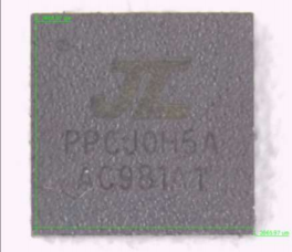 Label of main unit (Model: AC981A)
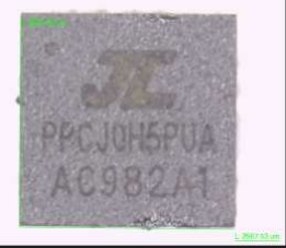 Label of main unit (Model: AC982A)
7 PHOTO DOCUMENT
Model: AC981A
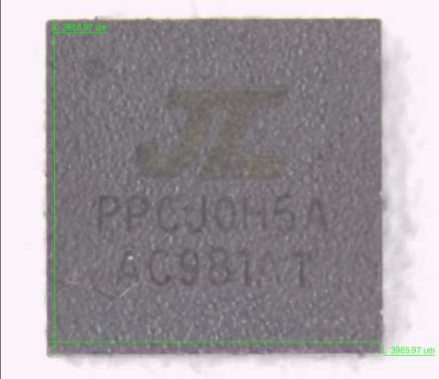
Figure 1. Overall view (AC981A)
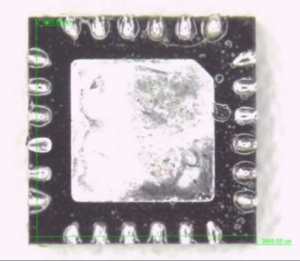
Figure 2. Overall view (AC981A)
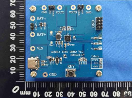
Figure 3. Internal view (Test Board – top)
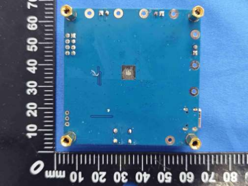
Figure 4. Internal view (Test Board – bottom)
Model: AC982A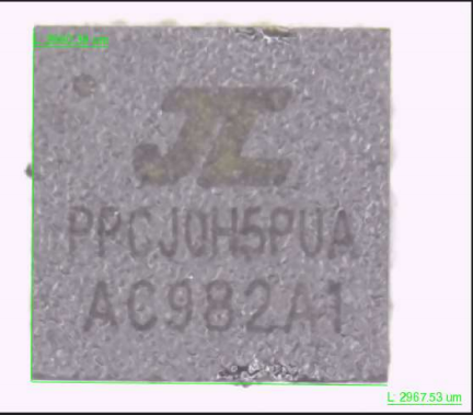
Figure 5. Overall view (AC982A)
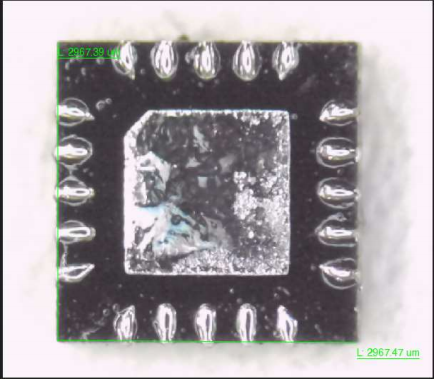
Figure 6. Overall view (AC982A)
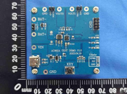
Figure 7. Internal view (Test Board – top)
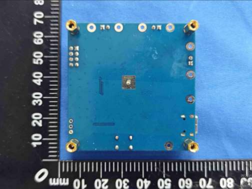
Figure 8. Internal view (Test Board – bottom)
Statement
- The laboratory guarantees the scientificity, accuracy and impartiality of the test, and is responsible fo all the information in the report, except the information provided by the customer. The customer is responsible for the impact of the information provided on the validity of the results.
- The report without China inspection body and laboratory Mandatory Approval (CMA) mark has no effect of proving to the society.
- For the report with CNAS mark or A2LA mark , the items marked with "☆" are not within the accredite scope.
- This report is invalid if it is altered, without the signature of the testing and approval personnel , or without the “inspection and testing dedicated stamp” or test report stamp.
- The test data and results are only valid for the tested samples provided by the customer.
- This report shall not be partially reproduced without the written permission of the laboratory.
- Any objection shall be raised to the laboratory within 30 days after receiving the report.
r
d
--END OF REPORT--