211-21241263-000 TRF_CB_E
 | Test Report issued under the responsibility of: NCB TÜV SÜD PSB Pte. Ltd. 15 International Business Park TÜV SÜD @ IBP Singapore 609937 |  | |
|---|---|---|---|
| TEST REPORT IEC 62368-1 Audio/video, information and communication technology equipment Part 1: Safety requirements | |||
| Report Number............................... : 211-21241263-000 Date of issue................................... : 2024-10-09 Total number of pages .................. : 49 | |||
| Name of Testing Laboratory preparing the Report ..................... : | TÜV SÜD Certification and Testing (China) Co. , Ltd. Shenzhen Branch | ||
| Applicant’s name ........................... : Zhuhai Jieli Technology Co. , Ltd. Address........................................... : Jie Li Science and Technology Park, No. 333 Kexing Road, Nanping Town, Xiangzhou District, 519000 Zhuhai City, Guangdong Province, PEOPLE'S REPUBLIC OF CHINA | |||
| Test specification: Standard : IEC 62368-1:2018 Test procedure ............................... : CB Scheme Non-standard test method : N/A | |||
| TRF template used......................... : IECEE OD-2020-F1:2021 , Ed.1.4 Test Report Form No..................... : IEC62368_ 1E Test Report Form(s) Originator .... : UL(US) Master TRF...................................... : Dated 2022-04-14 Copyright © 2022 IEC System of Conformity Assessment Schemes for Electrotechnical Equipment and Components (IECEE System) . All rights reserved. This publication may be reproduced in whole or in part for non-commercial purposes as long as the IECEE is acknowledged as copyright owner and source of the material. IECEE takes no responsibility for and will not assume liability for damages resulting from the reader's interpretation of the reproduced material due to its placement and context. If this Test Report Form is used by non-IECEE members, the IECEE/IEC logo and the reference to the CB Scheme procedure shall be removed. This report is not valid as a CB Test Report unless signed by an approved CB Testing Laboratory and appended to a CB Test Certificate issued by an NCB in accordance with IECEE 02. | |||
| General disclaimer: The test results presented in this report relate only to the object tested. This report shall not be reproduced, except in full, without the written approval of the Issuing CB Testing Laboratory. The authenticity of this Test Report and its contents can be verified by contacting the NCB, responsible for this Test Report. | |||
| Test item description ....................... : Trade Mark(s) ................................ .. : Manufacturer : Model/Type reference ...................... : Ratings .............................................. : | IC Same as the applicant JL7006F , JL7003F , JL7003D , JL7006D , JL6973D , JL6976D , JL7083E, JL7083F , JL7083G , JL7086E, JL7086F , JL7086G , JL7096D , JL7096G , JL7096F , JL7094F , JL7094E, JL7094G , JL7093A, AC7196D 5.5VDC max (VPWR) | ||||
|---|---|---|---|---|---|
| Responsible Testing Laboratory (as applicable), testing procedure and testing location(s): | |||||
 | CB Testing Laboratory: | TÜV SÜD Certification and Testing (China) Co. , Ltd. Shenzhen Branch | |||
| Testing location/ address ............................ : | Building 12 & 13, Zhiheng Wisdomland Business Park, | ||||
| , Nantou, Nanshan District, Shenzhen, Guangdong 518052, China | |||||
| Tested by (name, function, signature) ....... : | Felix Zheng , Project Handler |  | |||
| Approved by (name, function, signature) .. : | Eason Wan, Designated Reviewer |  | |||
| Testing procedure: CTF Stage 1: | |||||
| Testing location/ address ............................ : | |||||
| Tested by (name, function, signature) ....... : | |||||
| Approved by (name, function, signature) .. : | |||||
| Testing procedure: CTF Stage 2: | |||||
| Testing location/ address ............................ : | |||||
| Tested by (name, function, signature) ........ : | |||||
| Witnessed by (name, function, signature) . : | |||||
| Approved by (name, function, signature) .. : | |||||
| Testing procedure: CTF Stage 3: | |||||
| Testing procedure: CTF Stage 4: | |||||
| Testing location/ address ............................ : | |||||
| Tested by (name, function, signature) ....... : | |||||
| Witnessed by (name, function, signature) . : | |||||
| Approved by (name, function, signature) .. : | |||||
| Supervised by (name, function, signature) : | |||||
Guankou Erlu
| List of Attachments (including a total number of pages in each attachment): Attachment No. 1: 22 pages of EUROPEAN GROUP DIFFERENCES AND NATIONAL DIFFERENCES for EN IEC 62368-1:2020+A11:2020 . Attachment No. 2: 57 pages of National and Group Differences for IEC 62368-1:2018 (Third Edition) as per CB Bulletin. Attachment No. 3: 1 page of appended table Annex G.9. Attachment No. 4: 6 pages of photo document. | |
|---|---|
| Summary of testing: | |
| Tests performed (name of test and test clause): The submitted samples were found to comply with the requirements of: -IEC 62368-1:2018 All applicable tests as described in the compliance checklist were performed at models JL7006F, JL7083G and JL7096D. | Testing location: TÜV SÜD Certification and Testing (China) Co. , Ltd. Shenzhen Branch Building 12 & 13, Zhiheng Wisdomland Business Park, Guankou Erlu, Nantou, Nanshan District, Shenzhen, Guangdong 518052, China |
| Summary of compliance with National Differences (List of countries addressed): See the attachment No. 1 and No. 2 of National and Group Differences for details. The product fulfils the requirements of EN IEC 62368-1:2020+A11:2020 . | |
| Use of uncertainty of measurement for decisions on conformity (decision rule): No decision rule is specified by the IEC standard, when comparing the measurement result with the applicable limit according to the specification in that standard. The decisions on conformity are made without applying the measurement uncertainty (“simple acceptance” decision rule, previously known as“accuracy method”) . Other: (to be specified, for example when required by the standard or client, or if national accreditation requirements apply) Information on uncertainty of measurement: The uncertainties of measurement are calculated by the laboratory based on application of criteria given by OD-5014 for test equipment and application of test methods, decision sheets and operational procedures of IECEE. IEC Guide 115 provides guidance on the application of measurement uncertainty principles and applying the decision rule when reporting test results within IECEE scheme, noting that the reporting of the measurement uncertainty for measurements is not necessary unless required by the test standard or customer. Calculations leading to the reported values are on file with the NCB and testing laboratory that conducted the testing. |
Copy of marking plate:
The artwork below may be only a draft. The use of certification marks on a product must be authorized by the respective NCBs that own these marks.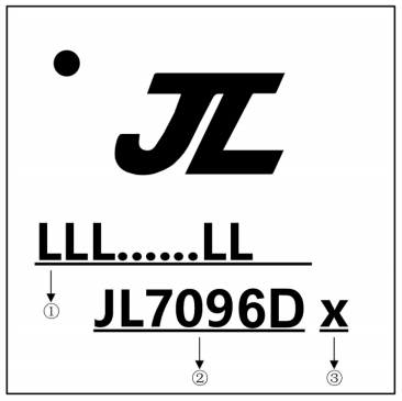 (Marking on IC’s body)
Notes:
① “LLL LL” may be 7 to 18 alphanumerics , indicates LOT No. ;
② Chip Model, which can be replaced by others listed in this report.
③ “x” may be 0, 2, 3, 4 , 5, 6, 7 or 8 , indicates built-in flash size:
0: No Flash Memory;
2: 2Mbit Flash;
4: 4Mbit Flash;
8: 8Mbit Flash;
6: 16Mbit Flash;
3: 32Mbit Flash;
5: 64Mbit Flash;
7: 128Mbit Flash.
Remark: The above markings are the minimum requirements required by the safety standard. For the final production samples, the additional markings which do not give rise to misunderstanding may be added.
Test item particulars:
Product group .....................................................: end product built-in component
Classification of use by ......................................: Ordinary person Children likely present
Instructed person
Skilled person
Supply connection...............................................: AC mains DC mains
not mains connected:
ES1 ES2 ES3
Supply tolerance .................................................: +10%/-10%
+20%/-15%
- %/ - %
None (Not directly connected to the mains) Supply connection – type ..................................: pluggable equipment type A
non-detachable supply cord
appliance coupler
direct plug-in
pluggable equipment type B
non-detachable supply cord
appliance coupler
permanent connection
mating connector
other: Not directly connected to the mains Considered current rating of protective --A;
device................................................................ . : Location: building equipment
N/A
Equipment mobility .......................................... : movable hand-held transportable
direct plug-in stationary for building-in
wall/ceiling-mounted SRME/rack-mounted other:
Overvoltage category (OVC) ........................... : OVC I OVC II OVC III
OVC IV
other: Not directly connected to the mains
Class of equipment ......................................... : Class I Class II Class III
Not classified
Special installation location ........................... : N/A restricted access area
outdoor location
Pollution degree (PD) ...................................... : PD 1 PD 2 PD 3
Manufacturer’s specified Tma........................... : 85 °C Outdoor: minimum °C
IP protection class ........................................... : IPX0 IP___
Power systems ................................................. : TN TT IT- V L-L
not AC mains
N/A (Not directly connected to the mains) Altitude during operation (m) ......................... : 2000 m or less 5000 m or less
Altitude of test laboratory (m) ........................ : 2000 m or less 500 m or less
Mass of equipment (kg) ................................ .. : Less than 1g
| Possible test case verdicts: -test case does not apply to the test object ....: N/A -test object does meet the requirement...........: P (Pass) -test object does not meet the requirement....: F (Fail) | |
|---|---|
| Testing: Date of receipt of test item .................................: 2024-08-30 Date (s) of performance of tests ........................: 2024-08-30 to 2024-10-09 | |
| General remarks: | |
| "(See Enclosure #)" refers to additional information appended to the report. "(See appended table)" refers to a table appended to the report. Throughout this report a口comma /区point is used as the decimal separator. For EU directives and regulations which have been harmonized with (EU) 2019/1020 in its Annex I, the name, registered trade name or registered trade mark, and contact details, including the postal address of the economic operator (EU manufacturer, EU importer, EU authorised representative, or EU fulfilment service provider where no other economic operator as mentioned in the first 3 options) shall be indicatedon the product or on its packing, the parcel or an accompanying document. | |
| Manufacturer’s Declaration per sub-clause 4.2.5 of IECEE 02: | |
| The application for obtaining a CB Test Certificate includes more than one factory location and a declaration from the Manufacturer stating that the sample(s) submitted for evaluation is (are) representative of the products from each factory has been provided ................................ ................: | Yes Not applicable |
| When differences exist; they shall be identified in the General product information section. | |
| Name and address of factory (ies) ................. : Same as the applicant |
General product information and other remarks:
- The EUT covered in this report is a highly integrated charge IC which used for Audio/video, information and communication technology equipment. It can monitor the charging status and regulate the output current accordingly.
- The EUT is a built-in component , when installed in final system, suitable enclosure and type of supply connection should be provided and all requirement of mentioned standard must be fulfilled.
- The EUT shall be supplied by ES1/PS2 power source, which is separated from ES3 mains by double/ reinforced insulation.
- The EUT is a built-in component , temperature of accessible surface should be considered in the final system.
- Specified maximum ambient temperature is 85°C.
- During the tests, the EUT was mounted on the demo board provided by the manufacturer.
- Models JL7006F , JL7003F , JL7003D , JL7006D , JL6973D and JL6976D are identical except for different model number and IC package , which not affect charging function.
Models JL7083E, JL7083F, JL7083G, JL7086E, JL7086F and JL7086G are identical except for different model number and IC package , which not affect charging function.
Models JL7096D , JL7096G , JL7096F , JL7094F , JL7094E, JL7094G , JL7093A and AC7196D are identical except for different model number and IC package , which not affect charging function.
Models JL7006F , JL7083G and JL7096D are identical except for model number, IC package , rated charging current and steps of charging current.
Unless otherwise specified, the models JL7006F , JL7083G and JL7096D mounted on the demo boards were selected as representative for all tests.
8. The ratings of IC refer to below table:
| Charging Mode Model number | Input Voltage (VDC) | VBAT Charging Voltage (VDC) | VBAT Charging Current (A) | VBAT Rated Charging Current (A) |
|---|---|---|---|---|
| Max. | Max. | Max. | ||
| JL7006F , JL7003F , JL7003D , JL7006D , JL6973D , JL6976D | 5.5 | 4.5 | 0.21 | 0.20 |
| JL7083E, JL7083F, JL7083G, JL7086E, JL7086F, JL7086G | 5.5 | 4.5 | 0.23 | 0.22 |
| JL7096D , JL7096G , JL7096F , JL7094F , JL7094E, JL7094G , JL7093A, AC7196D | 5.5 | 4.5 | 0.21 | 0.18 |
General product information and other remarks (Continued):
9. See below IC package for each model:
| Model No. | IC package | Model No. | IC package |
|---|---|---|---|
| JL7006F | 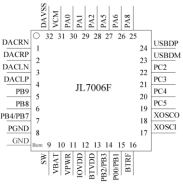 | JL7003F | 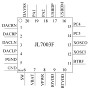 |
| JL7003D | 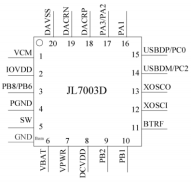 | JL7006D | 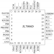 |
| JL6973D | 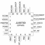 | JL6976D | 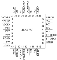 |
| JL7083E | 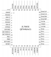 | JL7083F | 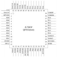 |
General product information and other remarks (Continued):
| Model No. | IC package | Model No. | IC package |
|---|---|---|---|
| JL7083G | 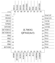 | JL7086E | 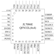 |
| JL7086F | 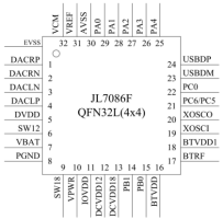 | JL7086G | 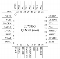 |
| JL7096D | 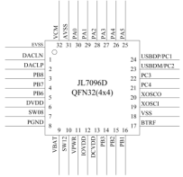 | JL7096G | 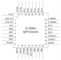 |
| JL7096F | 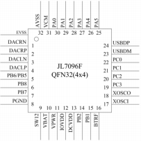 | JL7094F | 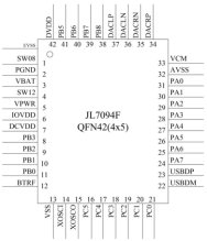 |
General product information and other remarks (Continued):
| Model No. | IC package | Model No. | IC package |
|---|---|---|---|
| JL7094E | 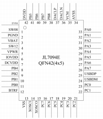 | JL7094G | 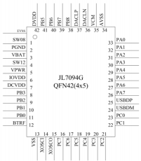 |
| JL7093A | 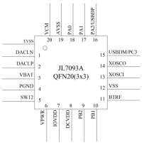 | AC7196D | 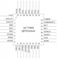 |
| OVERVIEW OF ENERGY SOURCES AND SAFEGUARDS | ||||
|---|---|---|---|---|
| Clause | Possible Hazard | |||
| 5 | Electrically-caused injury | |||
| Class and Energy Source (e.g. ES3: Primary circuit) | Body Part (e.g. Ordinary) | Safeguards | ||
| B | S | R | ||
| ES1: All circuits including supplying circuits | Skilled person | N/A | N/A | N/A |
| 6 | Electrically-caused fire | |||
| Class and Energy Source (e.g. PS2: 100 Watt circuit) | Material part (e.g. Printed board) | Safeguards | ||
| B | 1st S | 2nd S | ||
| PS2: Power source circuits | Internal combustible material | N/A* | N/A* | N/A* |
| Output of IC (Built-in component , to be evaluated in the final system) | N/A | N/A | N/A | N/A |
| 7 | Injury caused by hazardous substances | |||
| Class and Energy Source (e.g. Ozone) | Body Part (e.g. , Skilled) | Safeguards | ||
| B | S | R | ||
| N/A | N/A | N/A | N/A | N/A |
| 8 | Mechanically-caused injury | |||
| Class and Energy Source (e.g. MS3: Plastic fan blades) | Body Part (e.g. Ordinary) | Safeguards | ||
| B | S | R | ||
| Edges and corners of accessible parts; Equipment mass (Built-in component , to be evaluated in the final system) | Skilled person | N/A | N/A | N/A |
| 9 | Thermal burn | |||
| Class and Energy Source (e.g. TS1: Keyboard caps) | Body Part (e.g. , Ordinary) | Safeguards | ||
| B | S | R | ||
| Accessible parts (Built-in component , to be evaluated in the final system) | Skilled person | N/A | N/A | N/A |
| 10 | Radiation | |||
| Class and Energy Source (e.g. RS1: PMP sound output) | Body Part (e.g. , Ordinary) | Safeguards | ||
| B | S | R | ||
| N/A | N/A | N/A | N/A | N/A |
| Supplementary Information: “B” – Basic Safeguard; “S” – Supplementary Safeguard; “R” – Reinforced Safeguard“N” – Normal Condition; “A” – Abnormal Condition * Built-in component, to be evaluated in the final system. |
| ENERGY SOURCE DIAGRAM |
|---|
| Optional. Manufacturers are to provide the energy sources diagram identify declared energy sources and identifying the demarcations are between power sources. Recommend diagram be provided included in power supply and multipart systems. Insert diagram below. Example diagram designs are; Block diagrams; image(s) with layered data; mechanical drawings |
| 口 ES 口 PS 口 MS 口TS 口 RS Remark: see above table “OVERVIEW OF ENERGY SOURCES AND SAFEGUARDS” for details. |
| 4 | GENERAL REQUIREMENTS | P | |
|---|---|---|---|
| 4.1.1 | Acceptance of materials, components and subassemblies | P | |
| 4.1.2 | Use of components | P | |
| 4.1.3 | Equipment design and construction | P | |
| 4.1.4 | Specified ambient temperature for outdoor use (oC) ................................ ................................ .................... : | N/A | |
| 4.1.5 | Constructions and components not specifically covered | N/A | |
| 4.1.8 | Liquids and liquid filled components (LFC) | N/A | |
| 4.1.15 | Markings and instructions | (See Annex F) | P |
| 4.4.3 | Safeguard robustness | Built-in component , to be evaluated in the final system | N/A |
| 4.4.3.1 | General | N/A | |
| 4.4.3.2 | Steady force tests | N/A | |
| 4.4.3.3 | Drop tests | N/A | |
| 4.4.3.4 | Impact tests | N/A | |
| 4.4.3.5 | Internal accessible safeguard tests | N/A | |
| 4.4.3.6 | Glass impact tests | N/A | |
| 4.4.3.7 | Glass fixation tests | N/A | |
| Glass impact test (1J) | N/A | ||
| Push/pull test (10 N) | N/A | ||
| 4.4.3.8 | Thermoplastic material tests | N/A | |
| 4.4.3.9 | Air comprising a safeguard | N/A | |
| 4.4.3.10 | Accessibility, glass, safeguard effectiveness | N/A | |
| 4.4.4 | Displacement of a safeguard by an insulating liquid | N/A | |
| 4.4.5 | Safety interlocks | N/A | |
| 4.5 | Explosion | N/A | |
| 4.5.1 | General | N/A | |
| 4.5.2 | No explosion during normal/abnormal operating condition | N/A | |
| No harm by explosion during single fault conditions | N/A | ||
| 4.6 | Fixing of conductors | N/A | |
| Fix conductors not to defeat a safeguard | N/A | ||
| Compliance is checked by test .............................. : | N/A | ||
| 4.7 | Equipment for direct insertion into mains socket–outlets | N/A | |
| 4.7.2 | Mains plug part complies with relevant standard .. : | N/A |
| 4.7.3 | Torque (Nm) ................................ .......................... : | N/A | |
|---|---|---|---|
| 4.8 | Equipment containing coin/button cell batteries | N/A | |
| 4.8.1 | General | N/A | |
| 4.8.2 | Instructional safeguard ................................ .......... : | N/A | |
| 4.8.3 | Battery compartment door/cover construction | N/A | |
| Open torque test | N/A | ||
| 4.8.4.2 | Stress relief test | N/A | |
| 4.8.4.3 | Battery replacement test | N/A | |
| 4.8.4.4 | Drop test | N/A | |
| 4.8.4.5 | Impact test | N/A | |
| 4.8.4.6 | Crush test | N/A | |
| 4.8.5 | Compliance | N/A | |
| 30N force test with test probe | N/A | ||
| 20N force test with test hook | N/A | ||
| 4.9 | Likelihood of fire or shock due to entry of conductive object | N/A | |
| 4.10 | Component requirements | N/A | |
| 4.10.1 | Disconnect Device | N/A | |
| 4.10.2 | Switches and relays | N/A |
| 5 | ELECTRICALLY-CAUSED INJURY | P | |
|---|---|---|---|
| 5.2 | Classification and limits of electrical energy sources | P | |
| 5.2.2 | ES1, ES2 and ES3 limits | P | |
| 5.2.2.2 | Steady-state voltage and current limits .................... : | (See appended table 5.2) | P |
| 5.2.2.3 | Capacitance limits ................................ ..................... : | N/A | |
| 5.2.2.4 | Single pulse limits ................................ ..................... : | No single pulse introduced | N/A |
| 5.2.2.5 | Limits for repetitive pulses ................................ : | No repetitive pulses introduced | N/A |
| 5.2.2.6 | Ringing signals | No means for connection to telephone network and no ringing signal generated | N/A |
| 5.2.2.7 | Audio signals | N/A | |
| 5.3 | Protection against electrical energy sources | P | |
| 5.3.1 | General Requirements for accessible parts to ordinary, instructed and skilled persons | All circuits including supplying circuits were considered as ES1 | P |
| 5.3.1 a) | Accessible ES1/ES2 derived from ES2/ES3 circuits | N/A | |
| 5.3.1 b) | Skilled persons not unintentional contact ES3 bare conductors | N/A |
| 5.3.2.1 | Accessibility to electrical energy sources and safeguards | N/A | |
|---|---|---|---|
| Accessibility to outdoor equipment bare parts | N/A | ||
| 5.3.2.2 | Contact requirements | N/A | |
| Test with test probe from Annex V | _ | ||
| 5.3.2.2 a) | Air gap – electric strength test potential (V) ............. : | N/A | |
| 5.3.2.2 b) | Air gap – distance (mm) ................................ ........... : | N/A | |
| 5.3.2.3 | Compliance | N/A | |
| 5.3.2.4 | Terminals for connecting stripped wire | N/A | |
| 5.4 | Insulation materials and requirements | N/A | |
| 5.4.1.2 | Properties of insulating material | N/A | |
| 5.4.1.3 | Material is non-hygroscopic | N/A | |
| 5.4.1.4 | Maximum operating temperature for insulating materials ................................ ................................ : | N/A | |
| 5.4.1.5 | Pollution degrees ...................................................... : | N/A | |
| 5.4.1.5.2 | Test for pollution degree 1 environment and for an insulating compound | N/A | |
| 5.4.1.5.3 | Thermal cycling test | N/A | |
| 5.4.1.6 | Insulation in transformers with varying dimensions | N/A | |
| 5.4.1.7 | Insulation in circuits generating starting pulses | N/A | |
| 5.4.1.8 | Determination of working voltage ............................. : | N/A | |
| 5.4.1.9 | Insulating surfaces | N/A | |
| 5.4.1.10 | Thermoplastic parts on which conductive metallic parts are directly mounted | N/A | |
| 5.4.1.10.2 | Vicat test ................................ ................................ : | N/A | |
| 5.4.1.10.3 | Ball pressure test ...................................................... : | N/A | |
| 5.4.2 | Clearances | N/A | |
| 5.4.2.1 | General requirements | N/A | |
| Clearances in circuits connected to AC Mains, Alternative method | N/A | ||
| 5.4.2.2 | Procedure 1 for determining clearance | N/A | |
| Temporary overvoltage ................................ ............ : | _ | ||
| 5.4.2.3 | Procedure 2 for determining clearance | N/A | |
| 5.4.2.3.2.2 | a.c. mains transient voltage ................................ ...... : | _ | |
| 5.4.2.3.2.3 | d.c. mains transient voltage ................................ ..... : | _ | |
| 5.4.2.3.2.4 | External circuit transient voltage............................... : | _ |
| 5.4.2.3.2.5 | Transient voltage determined by measurement ......: | _ | |
|---|---|---|---|
| 5.4.2.4 | Determining the adequacy of a clearance using an electric strength test ................................ ................. : | N/A | |
| 5.4.2.5 | Multiplication factors for clearances and test voltages ................................ ................................ ................... : | N/A | |
| 5.4.2.6 | Clearance measurement ................................ : | N/A | |
| 5.4.3 | Creepage distances | N/A | |
| 5.4.3.1 | General | N/A | |
| 5.4.3.3 | Material group ................................ ........................... : | _ | |
| 5.4.3.4 | Creepage distances measurement .......................... : | N/A | |
| 5.4.4 | Solid insulation | N/A | |
| 5.4.4.1 | General requirements | N/A | |
| 5.4.4.2 | Minimum distance through insulation ...................... : | N/A | |
| 5.4.4.3 | Insulating compound forming solid insulation | N/A | |
| 5.4.4.4 | Solid insulation in semiconductor devices | N/A | |
| 5.4.4.5 | Insulating compound forming cemented joints | N/A | |
| 5.4.4.6 | Thin sheet material | N/A | |
| 5.4.4.6.1 | General requirements | N/A | |
| 5.4.4.6.2 | Separable thin sheet material | N/A | |
| Number of layers (pcs) ................................ ............ : | N/A | ||
| 5.4.4.6.3 | Non-separable thin sheet material | N/A | |
| Number of layers (pcs) ................................ ......... : | N/A | ||
| 5.4.4.6.4 | Standard test procedure for non-separable thin sheet material ................................ ........................ : | N/A | |
| 5.4.4.6.5 | Mandrel test | N/A | |
| 5.4.4.7 | Solid insulation in wound components | N/A | |
| 5.4.4.9 | Solid insulation at frequencies >30 kHz, EP, KR, d, VPW (V) ................................ ................................ ... : | N/A | |
| Alternative by electric strength test, tested voltage (V), KR ................................ ................................ : | N/A | ||
| 5.4.5 | Antenna terminal insulation | N/A | |
| 5.4.5.1 | General | N/A | |
| 5.4.5.2 | Voltage surge test | N/A | |
| 5.4.5.3 | Insulation resistance (MΩ) ................................ : | N/A | |
| Electric strength test ................................ ................. : | N/A | ||
| 5.4.6 | Insulation of internal wire as part of supplementary safeguard | N/A |
| 5.4.7 | Tests for semiconductor components and for cemented joints | N/A | |
|---|---|---|---|
| 5.4.8 | Humidity conditioning | N/A | |
| Relative humidity (%), temperature (°C), duration (h) ................................ ................................ .......... : | _ | ||
| 5.4.9 | Electric strength test | N/A | |
| 5.4.9.1 | Test procedure for type test of solid insulation : | N/A | |
| 5.4.9.2 | Test procedure for routine test | N/A | |
| 5.4.10 | Safeguards against transient voltages from external circuits | N/A | |
| 5.4.10.1 | Parts and circuits separated from external circuits | N/A | |
| 5.4.10.2 | Test methods | N/A | |
| 5.4.10.2.1 | General | N/A | |
| 5.4.10.2.2 | Impulse test ................................ ........................... : | N/A | |
| 5.4.10.2.3 | Steady-state test ................................ .................... : | N/A | |
| 5.4.10.3 | Verification for insulation breakdown for impulse test ................................ ................................ ......... : | N/A | |
| 5.4.11 | Separation between external circuits and earth | N/A | |
| 5.4.11.1 | Exceptions to separation between external circuitsand earth | N/A | |
| 5.4.11.2 | Requirements | N/A | |
| SPDs bridge separation between external circuit and earth | N/A | ||
| Rated operating voltage Uop (V) ............................. : | _ | ||
| Nominal voltage Upeak (V) ................................ ....... : | _ | ||
| Max increase due to variation ΔUsp ........................ : | _ | ||
| Max increase due to ageing ΔUsa ......................... : | _ | ||
| 5.4.11.3 | Test method and compliance ................................ : | N/A | |
| 5.4.12 | Insulating liquid | N/A | |
| 5.4.12.1 | General requirements | N/A | |
| 5.4.12.2 | Electric strength of an insulating liquid .................. : | N/A | |
| 5.4.12.3 | Compatibility of an insulating liquid ....................... : | N/A | |
| 5.4.12.4 | Container for insulating liquid ................................ : | N/A | |
| 5.5 | Components as safeguards | N/A | |
| 5.5.1 | General | N/A | |
| 5.5.2 | Capacitors and RC units | N/A | |
| 5.5.2.1 | General requirement | N/A |
| 5.5.2.2 | Safeguards against capacitor discharge after disconnection of a connector................................ . : | N/A | |
|---|---|---|---|
| 5.5.3 | Transformers | N/A | |
| 5.5.4 | Optocouplers | N/A | |
| 5.5.5 | Relays | N/A | |
| 5.5.6 | Resistors | N/A | |
| 5.5.7 | SPDs | N/A | |
| 5.5.8 | Insulation between the mains and an external circuit consisting of a coaxial cable ....................... : | N/A | |
| 5.5.9 | Safeguards for socket-outlets in outdoor equipment | N/A | |
| RCD rated residual operating current (mA) ........... : | _ | ||
| 5.6 | Protective conductor | N/A | |
| 5.6.2 | Requirement for protective conductors | N/A | |
| 5.6.2.1 | General requirements | N/A | |
| 5.6.2.2 | Colour of insulation | N/A | |
| 5.6.3 | Requirement for protective earthing conductors | N/A | |
| Protective earthing conductor size (mm2) .............. : | _ | ||
| Protective earthing conductor serving as a reinforced safeguard | N/A | ||
| Protective earthing conductor serving as a double safeguard | N/A | ||
| 5.6.4 | Requirements for protective bonding conductors | N/A | |
| 5.6.4.1 | Protective bonding conductors | N/A | |
| Protective bonding conductor size (mm2) . .............. : | _ | ||
| 5.6.4.2 | Protective current rating (A) ................................ : | N/A | |
| 5.6.5 | Terminals for protective conductors | N/A | |
| 5.6.5.1 | Terminal size for connecting protective earthing conductors (mm) ................................ .................... : | N/A | |
| Terminal size for connecting protective bonding conductors (mm) ....................................................... : | N/A | ||
| 5.6.5.2 | Corrosion | N/A | |
| 5.6.6 | Resistance of the protective bonding system | N/A | |
| 5.6.6.1 | Requirements | N/A | |
| 5.6.6.2 | Test Method ................................ ........................... : | N/A | |
| 5.6.6.3 | Resistance (Ω) or voltage drop.............................. : | N/A | |
| 5.6.7 | Reliable connection of a protective earthing conductor | N/A |
| 5.6.8 | Functional earthing | N/A | |
|---|---|---|---|
| Conductor size (mm2) ................................ ............. : | N/A | ||
| Class II with functional earthing marking .............. : | N/A | ||
| Appliance inlet cl & cr (mm) ................................ ... : | N/A | ||
| 5.7 | Prospective touch voltage, touch current and protective conductor current | N/A | |
| 5.7.2 | Measuring devices and networks | N/A | |
| 5.7.2.1 | Measurement of touch current | N/A | |
| 5.7.2.2 | Measurement of voltage | N/A | |
| 5.7.3 | Equipment set-up, supply connections and earth connections | N/A | |
| 5.7.4 | Unearthed accessible parts ................................ ... : | N/A | |
| 5.7.5 | Earthed accessible conductive parts ..................... : | N/A | |
| 5.7.6 | Requirements when touch current exceeds ES2 limits | N/A | |
| Protective conductor current (mA) ......................... : | N/A | ||
| Instructional Safeguard................................ .......... : | N/A | ||
| 5.7.7 | Prospective touch voltage and touch current associated with external circuits | N/A | |
| 5.7.7.1 | Touch current from coaxial cables | N/A | |
| 5.7.7.2 | Prospective touch voltage and touch current associated with paired conductor cables | N/A | |
| 5.7.8 | Summation of touch currents from external circuits | N/A | |
| a) Equipment connected to earthed external circuits, current (mA) ................................ ............. : | N/A | ||
| b) Equipment connected to unearthed external circuits, current (mA) ................................ ............. : | N/A | ||
| 5.8 | Backfeed safeguard in battery backed up supplies | N/A | |
| Mains terminal ES ................................ ..................... : | N/A | ||
| Air gap (mm) ................................ ............................. : | N/A |
| 6 | ELECTRICALLY-CAUSED FIRE | P | |
|---|---|---|---|
| 6.2 | Classification of PS and PIS | P | |
| 6.2.2 | Power source circuit classifications .......................... : | (See appended table 6.2.2) | P |
| 6.2.3 | Classification of potential ignition sources | Built-in component , to be evaluated in the final system | N/A |
| 6.2.3.1 | Arcing PIS ................................ ................................ : | N/A | |
| 6.2.3.2 | Resistive PIS ................................ ............................ : | N/A |
| 6.3 | Safeguards against fire under normal operating and abnormal operating conditions | N/A | |
|---|---|---|---|
| 6.3.1 | No ignition and attainable temperature value less than 90 % defined by ISO 871 or less than 300 oC for unknown materials ................................ ........... : | Built-in component , to be evaluated in the final system | N/A |
| Combustible materials outside fire enclosure : | N/A | ||
| 6.4 | Safeguards against fire under single fault conditions | N/A | |
| 6.4.1 | Safeguard method | Built-in component , to be evaluated in the final system | N/A |
| 6.4.2 | Reduction of the likelihood of ignition under single fault conditions in PS1 circuits | N/A | |
| 6.4.3 | Reduction of the likelihood of ignition under single fault conditions in PS2 and PS3 circuits | N/A | |
| 6.4.3.1 | Supplementary safeguards | N/A | |
| 6.4.3.2 | Single Fault Conditions ................................ .......... : | N/A | |
| Special conditions for temperature limited by fuse | N/A | ||
| 6.4.4 | Control of fire spread in PS1 circuits | N/A | |
| 6.4.5 | Control of fire spread in PS2 circuits | N/A | |
| 6.4.5.2 | Supplementary safeguards | N/A | |
| 6.4.6 | Control of fire spread in PS3 circuits | N/A | |
| 6.4.7 | Separation of combustible materials from a PIS | N/A | |
| 6.4.7.2 | Separation by distance | N/A | |
| 6.4.7.3 | Separation by a fire barrier | N/A | |
| 6.4.8 | Fire enclosures and fire barriers | N/A | |
| 6.4.8.2 | Fire enclosure and fire barrier material properties | N/A | |
| 6.4.8.2.1 | Requirements for a fire barrier | N/A | |
| 6.4.8.2.2 | Requirements for a fire enclosure | N/A | |
| 6.4.8.3 | Constructional requirements for a fire enclosure and a fire barrier | N/A | |
| 6.4.8.3.1 | Fire enclosure and fire barrier openings | N/A | |
| 6.4.8.3.2 | Fire barrier dimensions | N/A | |
| 6.4.8.3.3 | Top openings and properties | N/A | |
| Openings dimensions (mm) ................................ ... : | N/A | ||
| 6.4.8.3.4 | Bottom openings and properties | N/A | |
| Openings dimensions (mm) ................................ ... : | N/A | ||
| Flammability tests for the bottom of a fire enclosure | N/A | ||
| Instructional Safeguard ................................ ............. : | N/A |
| 6.4.8.3.5 | Side openings and properties | N/A | |
|---|---|---|---|
| Openings dimensions (mm) ................................ ... : | N/A | ||
| 6.4.8.3.6 | Integrity of a fire enclosure, condition met: a), b) or c) ................................ ................................ ............ : | N/A | |
| 6.4.8.4 | Separation of a PIS from a fire enclosure and a fire barrier distance (mm) or flammability rating .......... : | N/A | |
| 6.4.9 | Flammability of insulating liquid .............................. : | N/A | |
| 6.5 | Internal and external wiring | N/A | |
| 6.5.1 | General requirements | N/A | |
| 6.5.2 | Requirements for interconnection to building wiring ................................ ................................ ............... : | N/A | |
| 6.5.3 | Internal wiring size (mm2) for socket-outlets.......... : | N/A | |
| 6.6 | Safeguards against fire due to the connection to additional equipment | N/A |
| 7 | INJURY CAUSED BY HAZARDOUS SUBSTANCES | N/A | |
|---|---|---|---|
| 7.2 | Reduction of exposure to hazardous substances | N/A | |
| 7.3 | Ozone exposure | N/A | |
| 7.4 | Use of personal safeguards or personal protective equipment (PPE) | N/A | |
| Personal safeguards and instructions ................... : | _ | ||
| 7.5 | Use of instructional safeguards and instructions | N/A | |
| Instructional safeguard (ISO 7010) ....................... : | _ | ||
| 7.6 | Batteries and their protection circuits | N/A |
| 8 | MECHANICALLY-CAUSED INJURY | N/A | |
|---|---|---|---|
| 8.2 | Mechanical energy source classifications | N/A | |
| 8.3 | Safeguards against mechanical energy sources | N/A | |
| 8.4 | Safeguards against parts with sharp edges and corners | N/A | |
| 8.4.1 | Safeguards | Built-in component , to be evaluated in the final system | N/A |
| Instructional Safeguard ................................ ............. : | N/A | ||
| 8.4.2 | Sharp edges or corners | N/A | |
| 8.5 | Safeguards against moving parts | N/A | |
| 8.5.1 | Fingers, jewellery, clothing, hair, etc. , contact with MS2 or MS3 parts | N/A | |
| MS2 or MS3 part required to be accessible for the function of the equipment | N/A | ||
| Moving MS3 parts only accessible to skilled person | N/A |
| 8.5.2 | Instructional safeguard ................................ ............. : | N/A | |
|---|---|---|---|
| 8.5.4 | Special categories of equipment containing moving parts | N/A | |
| 8.5.4.1 | General | N/A | |
| 8.5.4.2 | Equipment containing work cells with MS3 parts | N/A | |
| 8.5.4.2.1 | Protection of persons in the work cell | N/A | |
| 8.5.4.2.2 | Access protection override | N/A | |
| 8.5.4.2.2.1 | Override system | N/A | |
| 8.5.4.2.2.2 | Visual indicator | N/A | |
| 8.5.4.2.3 | Emergency stop system | N/A | |
| Maximum stopping distance from the point of activation (m) ................................ ............................. : | N/A | ||
| Space between end point and nearest fixed mechanical part (mm) ................................ ............... : | N/A | ||
| 8.5.4.2.4 | Endurance requirements | N/A | |
| Mechanical system subjected to 100 000 cycles of operation | N/A | ||
| -Mechanical function check and visual inspection | N/A | ||
| -Cable assembly ...................................................... : | N/A | ||
| 8.5.4.3 | Equipment having electromechanical device for destruction of media | N/A | |
| 8.5.4.3.1 | Equipment safeguards | N/A | |
| 8.5.4.3.2 | Instructional safeguards against moving parts : | N/A | |
| 8.5.4.3.3 | Disconnection from the supply | N/A | |
| 8.5.4.3.4 | Cut type and test force (N) ................................ : | N/A | |
| 8.5.4.3.5 | Compliance | N/A | |
| 8.5.5 | High pressure lamps | N/A | |
| Explosion test ................................ ............................ : | N/A | ||
| 8.5.5.3 | Glass particles dimensions (mm) ............................. : | N/A | |
| 8.6 | Stability of equipment | N/A | |
| 8.6.1 | General | N/A | |
| Instructional safeguard ................................ ............. : | N/A | ||
| 8.6.2 | Static stability | N/A | |
| 8.6.2.2 | Static stability test ................................ ..................... : | N/A | |
| 8.6.2.3 | Downward force test | N/A | |
| 8.6.3 | Relocation stability | N/A |
| Wheels diameter (mm) ................................ ............. : | _ | ||
|---|---|---|---|
| Tilt test | N/A | ||
| 8.6.4 | Glass slide test | N/A | |
| 8.6.5 | Horizontal force test ................................ .................. : | N/A | |
| 8.7 | Equipment mounted to wall, ceiling or other structure | N/A | |
| 8.7.1 | Mount means type ................................ .................... : | N/A | |
| 8.7.2 | Test methods | N/A | |
| Test 1, additional downwards force (N) .................... : | N/A | ||
| Test 2, number of attachment points and test force (N) ................................ ................................ .............. : | N/A | ||
| Test 3 Nominal diameter (mm) and applied torque (Nm) ................................ ................................ ........... : | N/A | ||
| 8.8 | Handles strength | N/A | |
| 8.8.1 | General | N/A | |
| 8.8.2 | Handle strength test | N/A | |
| Number of handles................................ .................... : | _ | ||
| Force applied (N) ...................................................... : | _ | ||
| 8.9 | Wheels or casters attachment requirements | N/A | |
| 8.9.2 | Pull test | N/A | |
| 8.10 | Carts, stands and similar carriers | N/A | |
| 8.10.1 | General | N/A | |
| 8.10.2 | Marking and instructions ................................ ........... : | N/A | |
| 8.10.3 | Cart, stand or carrier loading test | N/A | |
| Loading force applied (N) ................................ : | N/A | ||
| 8.10.4 | Cart, stand or carrier impact test | N/A | |
| 8.10.5 | Mechanical stability | N/A | |
| Force applied (N) ...................................................... : | _ | ||
| 8.10.6 | Thermoplastic temperature stability | N/A | |
| 8.11 | Mounting means for slide-rail mounted equipment (SRME) | N/A | |
| 8.11.1 | General | N/A | |
| 8.11.2 | Requirements for slide rails | N/A | |
| Instructional Safeguard ................................ ............. : | N/A | ||
| 8.11.3 | Mechanical strength test | N/A | |
| 8.11.3.1 | Downward force test, force (N) applied.................... : | N/A | |
| 8.11.3.2 | Lateral push force test | N/A |
| 8.11.3.3 | Integrity of slide rail end stops | N/A | |
|---|---|---|---|
| 8.11.4 | Compliance | N/A | |
| 8.12 | Telescoping or rod antennas | N/A | |
| Button/ball diameter (mm) ................................ : | _ |
| 9 | THERMAL BURN INJURY | N/A | |
|---|---|---|---|
| 9.2 | Thermal energy source classifications | N/A | |
| 9.3 | Touch temperature limits | N/A | |
| 9.3.1 | Touch temperatures of accessible parts .................. : | Built-in component , to be evaluated in the final system | N/A |
| 9.3.2 | Test method and compliance | N/A | |
| 9.4 | Safeguards against thermal energy sources | N/A | |
| 9.5 | Requirements for safeguards | N/A | |
| 9.5.1 | Equipment safeguard | N/A | |
| 9.5.2 | Instructional safeguard ................................ ............. : | N/A | |
| 9.6 | Requirements for wireless power transmitters | N/A | |
| 9.6.1 | General | N/A | |
| 9.6.2 | Specification of the foreign objects | N/A | |
| 9.6.3 | Test method and compliance ................................ ... : | N/A |
| 10 | RADIATION | N/A | |
|---|---|---|---|
| 10.2 | Radiation energy source classification | N/A | |
| 10.2.1 | General classification | N/A | |
| Lasers ................................ ................................ : | _ | ||
| Lamps and lamp systems ................................ ...... : | _ | ||
| Image projectors ................................ .................... : | _ | ||
| X-Ray ................................ ................................ ..... : | _ | ||
| Personal music player ................................ ........... : | _ | ||
| 10.3 | Safeguards against laser radiation | N/A | |
| The standard(s) equipment containing laser(s) comply ................................ ................................ ....... : | N/A | ||
| 10.4 | Safeguards against optical radiation from lamps and lamp systems (including LED types) | N/A | |
| 10.4.1 | General requirements | N/A | |
| Instructional safeguard provided for accessible radiation level needs to exceed | N/A |
| Risk group marking and location .............................. : | N/A | ||
|---|---|---|---|
| Information for safe operation and installation | N/A | ||
| 10.4.2 | Requirements for enclosures | N/A | |
| UV radiation exposure ................................ .............. : | N/A | ||
| 10.4.3 | Instructional safeguard ................................ .......... : | N/A | |
| 10.5 | Safeguards against X-radiation | N/A | |
| 10.5.1 | Requirements | N/A | |
| Instructional safeguard for skilled persons ............ : | _ | ||
| 10.5.3 | Maximum radiation (pA/kg) ................................ : | _ | |
| 10.6 | Safeguards against acoustic energy sources | N/A | |
| 10.6.1 | General | N/A | |
| 10.6.2 | Classification | N/A | |
| Acoustic output LAeq,T, dB(A) ................................ : | N/A | ||
| Unweighted RMS output voltage (mV) .....................: | N/A | ||
| Digital output signal (dBFS) ................................ : | N/A | ||
| 10.6.3 | Requirements for dose-based systems | N/A | |
| 10.6.3.1 | General requirements | N/A | |
| 10.6.3.2 | Dose-based warning and automatic decrease | N/A | |
| 10.6.3.3 | Exposure-based warning and requirements | N/A | |
| 30 s integrated exposure level (MEL30) .................. : | N/A | ||
| Warning for MEL ≥ 100 dB(A) ................................ .. : | N/A | ||
| 10.6.4 | Measurement methods | N/A | |
| 10.6.5 | Protection of persons | N/A | |
| Instructional safeguards ................................ ........ : | N/A | ||
| 10.6.6 | Requirements for listening devices (headphones, earphones, etc. ) | N/A | |
| 10.6.6.1 | Corded listening devices with analogue input | N/A | |
| Listening device input voltage (mV) ...................... : | N/A | ||
| 10.6.6.2 | Corded listening devices with digital input | N/A | |
| Max. acoustic output LAeq,T, dB(A) ............................ : | N/A | ||
| 10.6.6.3 | Cordless listening devices | N/A | |
| Max. acoustic output LAeq,T, dB(A) ............................ : | N/A |
| B | NORMAL OPERATING CONDITION TESTS, ABNORMAL OPERATING CONDITION TESTS AND SINGLE FAULT CONDITION TESTS | N/A | |
|---|---|---|---|
| B.1 | General | N/A | |
| B.1.5 | Temperature measurement conditions | Built-in component , to be evaluated in the final system | N/A |
| B.2 | Normal operating conditions | N/A | |
| B.2.1 | General requirements ................................ ............ : | N/A | |
| Audio Amplifiers and equipment with audio amplifiers ................................ ............................... : | N/A | ||
| B.2.3 | Supply voltage and tolerances | N/A | |
| B.2.5 | Input test ................................ ................................ : | N/A | |
| B.3 | Simulated abnormal operating conditions | N/A | |
| B.3.1 | General | N/A | |
| B.3.2 | Covering of ventilation openings | N/A | |
| Instructional safeguard ................................ .......... : | N/A | ||
| B.3.3 | DC mains polarity test | N/A | |
| B.3.4 | Setting of voltage selector | N/A | |
| B.3.5 | Maximum load at output terminals | N/A | |
| B.3.6 | Reverse battery polarity | N/A | |
| B.3.7 | Audio amplifier abnormal operating conditions | N/A | |
| B.3.8 | Safeguards functional during and after abnormal operating conditions ................................ .............. : | N/A | |
| B.4 | Simulated single fault conditions | N/A | |
| B.4.1 | General | N/A | |
| B.4.2 | Temperature controlling device | N/A | |
| B.4.3 | Blocked motor test | N/A | |
| B.4.4 | Functional insulation | N/A | |
| B.4.4.1 | Short circuit of clearances for functional insulation | N/A | |
| B.4.4.2 | Short circuit of creepage distances for functional insulation | N/A | |
| B.4.4.3 | Short circuit of functional insulation on coated printed boards | N/A | |
| B.4.5 | Short-circuit and interruption of electrodes in tubesand semiconductors | N/A | |
| B.4.6 | Short circuit or disconnection of passive components | N/A | |
| B.4.7 | Continuous operation of components | N/A |
| B.4.8 | Compliance during and after single fault conditions ................................ ................................ ............... : | N/A | |
|---|---|---|---|
| B.4.9 | Battery charging and discharging under single fault conditions | N/A | |
| C | UV RADIATION | N/A | |
| C.1 | Protection of materials in equipment from UV radiation | N/A | |
| C.1.2 | Requirements | N/A | |
| C.1.3 | Test method | N/A | |
| C.2 | UV light conditioning test | N/A | |
| C.2.1 | Test apparatus ................................ ....................... : | N/A | |
| C.2.2 | Mounting of test samples | N/A | |
| C.2.3 | Carbon-arc light-exposure test | N/A | |
| C.2.4 | Xenon-arc light-exposure test | N/A | |
| D | TEST GENERATORS | N/A | |
| D.1 | Impulse test generators | N/A | |
| D.2 | Antenna interface test generator | N/A | |
| D.3 | Electronic pulse generator | N/A | |
| E | TEST CONDITIONS FOR EQUIPMENT CONTAINING AUDIO AMPLIFIERS | N/A | |
| E.1 | Electrical energy source classification for audio signals | N/A | |
| Maximum non-clipped output power (W) ............... : | _ | ||
| Rated load impedance (Ω) ................................ ... : | _ | ||
| Open-circuit output voltage (V) .............................. : | _ | ||
| Instructional safeguard ................................ .......... : | _ | ||
| E.2 | Audio amplifier normal operating conditions | N/A | |
| Audio signal source type ................................ ....... : | _ | ||
| Audio output power (W) ................................ ......... : | _ | ||
| Audio output voltage (V) ................................ ........ : | _ | ||
| Rated load impedance (Ω) ................................ ... : | _ | ||
| Requirements for temperature measurement | N/A | ||
| E.3 | Audio amplifier abnormal operating conditions | N/A | |
| F | EQUIPMENT MARKINGS, INSTRUCTIONS, AND INSTRUCTIONAL SAFEGUARDS | P | |
| F.1 | General | P | |
| Language ................................ .............................. : | English version | _ | |
| F.2 | Letter symbols and graphical symbols | N/A |
| F.2.1 | Letter symbols according to IEC60027-1 | N/A | |
|---|---|---|---|
| F.2.2 | Graphic symbols according to IEC, ISO or manufacturer specific | N/A | |
| F.3 | Equipment markings | P | |
| F.3.1 | Equipment marking locations | Located on IC’s body; built-in component, shall be also considered in end product | P |
| F.3.2 | Equipment identification markings | P | |
| F.3.2.1 | Manufacturer identification ................................ ... : | See copy of marking plate | P |
| F.3.2.2 | Model identification ................................ ............... : | See copy of marking plate | P |
| F.3.3 | Equipment rating markings | P | |
| F.3.3.1 | Equipment with direct connection to mains | N/A | |
| F.3.3.2 | Equipment without direct connection to mains | P | |
| F.3.3.3 | Nature of the supply voltage ................................ .. : | N/A | |
| F.3.3.4 | Rated voltage................................ ......................... : | N/A | |
| F.3.3.5 | Rated frequency ................................ .................... : | N/A | |
| F.3.3.6 | Rated current or rated power................................ . : | N/A | |
| F.3.3.7 | Equipment with multiple supply connections | N/A | |
| F.3.4 | Voltage setting device | N/A | |
| F.3.5 | Terminals and operating devices | N/A | |
| F.3.5.1 | Mains appliance outlet and socket-outlet markings ................................ ................................ ............... : | N/A | |
| F.3.5.2 | Switch position identification marking.................... : | N/A | |
| F.3.5.3 | Replacement fuse identification and rating markings ................................ ................................ ............... : | N/A | |
| Instructional safeguards for neutral fuse ............... : | N/A | ||
| F.3.5.4 | Replacement battery identification marking .......... : | N/A | |
| F.3.5.5 | Neutral conductor terminal | N/A | |
| F.3.5.6 | Terminal marking location | N/A | |
| F.3.6 | Equipment markings related to equipment classification | Class III Equipment | N/A |
| F.3.6.1 | Class I equipment | N/A | |
| F.3.6.1.1 | Protective earthing conductor terminal .................. : | N/A | |
| F.3.6.1.2 | Protective bonding conductor terminals ............... : | N/A | |
| F.3.6.2 | Equipment class marking ................................ ...... : | N/A | |
| F.3.6.3 | Functional earthing terminal marking .................... : | N/A |
| F.3.7 | Equipment IP rating marking ................................ . : | IPX0, no marking is needed; built-in component , also to be evaluated in final system | N/A |
|---|---|---|---|
| F.3.8 | External power supply output marking .................. : | N/A | |
| F.3.9 | Durability, legibility and permanence of marking | P | |
| F.3.10 | Test for permanence of markings | P | |
| F.4 | Instructions | P | |
| a) Information prior to installation and initial use | P | ||
| b) Equipment for use in locations where children not likely to be present | N/A | ||
| c) Instructions for installation and interconnection | P | ||
| d) Equipment intended for use only in restricted access area | N/A | ||
| e) Equipment intended to be fastened in place | N/A | ||
| f) Instructions for audio equipment terminals | N/A | ||
| g) Protective earthing used as a safeguard | N/A | ||
| h) Protective conductor current exceeding ES2 limits | N/A | ||
| i) Graphic symbols used on equipment | N/A | ||
| j) Permanently connected equipment not provided with all-pole mains switch | N/A | ||
| k) Replaceable components or modules providing safeguard function | N/A | ||
| l) Equipment containing insulating liquid | N/A | ||
| m) Installation instructions for outdoor equipment | N/A | ||
| F.5 | Instructional safeguards | N/A | |
| G | COMPONENTS | P | |
| G.1 | Switches | N/A | |
| G.1.1 | General | N/A | |
| G.1.2 | Ratings, endurance, spacing, maximum load | N/A | |
| G.1.3 | Test method and compliance | N/A | |
| G.2 | Relays | N/A | |
| G.2.1 | Requirements | N/A | |
| G.2.2 | Overload test | N/A | |
| G.2.3 | Relay controlling connectors supplying power to other equipment | N/A | |
| G.2.4 | Test method and compliance | N/A | |
| G.3 | Protective devices | N/A |
| G.3.1 | Thermal cut-offs | N/A | |
|---|---|---|---|
| Thermal cut-outs separately approved according to IEC 60730 with conditions indicated in a) & b) | N/A | ||
| Thermal cut-outs tested as part of the equipment as indicated in c) | N/A | ||
| G.3.1.2 | Test method and compliance | N/A | |
| G.3.2 | Thermal links | N/A | |
| G.3.2.1 | a) Thermal links tested separately according to IEC 60691 with specifics | N/A | |
| b) Thermal links tested as part of the equipment | N/A | ||
| G.3.2.2 | Test method and compliance | N/A | |
| G.3.3 | PTC thermistors | N/A | |
| G.3.4 | Overcurrent protection devices | N/A | |
| G.3.5 | Safeguards components not mentioned in G.3.1 to G.3.4 | N/A | |
| G.3.5.1 | Non-resettable devices suitably rated and marking provided | N/A | |
| G.3.5.2 | Single faults conditions ................................ .......... : | N/A | |
| G.4 | Connectors | N/A | |
| G.4.1 | Spacings | N/A | |
| G.4.2 | Mains connector configuration............................... : | N/A | |
| G.4.3 | Plug is shaped that insertion into mains socketoutlets or appliance coupler is unlikely | N/A | |
| G.5 | Wound components | N/A | |
| G.5.1 | Wire insulation in wound components | N/A | |
| G.5.1.2 | Protection against mechanical stress | N/A | |
| G.5.2 | Endurance test | N/A | |
| G.5.2.1 | General test requirements | N/A | |
| G.5.2.2 | Heat run test | N/A | |
| Test time (days per cycle) ................................ : | _ | ||
| Test temperature (oC) ................................ ............ : | _ | ||
| G.5.2.3 | Wound components supplied from the mains | N/A | |
| G.5.2.4 | No insulation breakdown | N/A | |
| G.5.3 | Transformers | N/A | |
| G.5.3.1 | Compliance method................................ ............... : | N/A | |
| Position ................................ ................................ .. : | N/A | ||
| Method of protection ................................ .............. : | N/A |
| G.5.3.2 | Insulation | N/A | |
|---|---|---|---|
| Protection from displacement of windings ............. : | _ | ||
| G.5.3.3 | Transformer overload tests | N/A | |
| G.5.3.3.1 | Test conditions | N/A | |
| G.5.3.3.2 | Winding temperatures | N/A | |
| G.5.3.3.3 | Winding temperatures-alternative test method | N/A | |
| G.5.3.4 | Transformers using FIW | N/A | |
| G.5.3.4.1 | General | N/A | |
| FIW wire nominal diameter ................................ : | _ | ||
| G.5.3.4.2 | Transformers with basic insulation only | N/A | |
| G.5.3.4.3 | Transformers with double insulation or reinforced insulation................................ ................................ : | N/A | |
| G.5.3.4.4 | Transformers with FIW wound on metal or ferrite core | N/A | |
| G.5.3.4.5 | Thermal cycling test and compliance | N/A | |
| G.5.3.4.6 | Partial discharge test | N/A | |
| G.5.3.4.7 | Routine test | N/A | |
| G.5.4 | Motors | N/A | |
| G.5.4.1 | General requirements | N/A | |
| G.5.4.2 | Motor overload test conditions | N/A | |
| G.5.4.3 | Running overload test | N/A | |
| G.5.4.4.2 | Locked-rotor overload test | N/A | |
| Test duration (days) ................................ .............. : | _ | ||
| G.5.4.5 | Running overload test for DC motors | N/A | |
| G.5.4.5.2 | Tested in the unit | N/A | |
| G.5.4.5.3 | Alternative method | N/A | |
| G.5.4.6 | Locked-rotor overload test for DC motors | N/A | |
| G.5.4.6.2 | Tested in the unit | N/A | |
| Maximum Temperature ................................ ........ : | N/A | ||
| G.5.4.6.3 | Alternative method | N/A | |
| G.5.4.7 | Motors with capacitors | N/A | |
| G.5.4.8 | Three-phase motors | N/A | |
| G.5.4.9 | Series motors | N/A | |
| Operating voltage ................................ ................. : | _ | ||
| G.6 | Wire Insulation | N/A |
| G.6.1 | General | N/A | |
|---|---|---|---|
| G.6.2 | Enamelled winding wire insulation | N/A | |
| G.7 | Mains supply cords | N/A | |
| G.7.1 | General requirements | N/A | |
| Type ................................ ................................ ....... : | _ | ||
| G.7.2 | Cross sectional area (mm2 or AWG) ..................... : | N/A | |
| G.7.3 | Cord anchorages and strain relief for nondetachable power supply cords | N/A | |
| G.7.3.2 | Cord strain relief | N/A | |
| G.7.3.2.1 | Requirements | N/A | |
| Strain relief test force (N) ................................ ....... : | N/A | ||
| G.7.3.2.2 | Strain relief mechanism failure | N/A | |
| G.7.3.2.3 | Cord sheath or jacket position, distance (mm) : | N/A | |
| G.7.3.2.4 | Strain relief and cord anchorage material | N/A | |
| G.7.4 | Cord Entry | N/A | |
| G.7.5 | Non-detachable cord bend protection | N/A | |
| G.7.5.1 | Requirements | N/A | |
| G.7.5.2 | Test method and compliance | N/A | |
| Overall diameter or minor overall dimension, D (mm) ................................ ................................ : | _ | ||
| Radius of curvature after test (mm) ....................... : | _ | ||
| G.7.6 | Supply wiring space | N/A | |
| G.7.6.1 | General requirements | N/A | |
| G.7.6.2 | Stranded wire | N/A | |
| G.7.6.2.1 | Requirements | N/A | |
| G.7.6.2.2 | Test with 8 mm strand | N/A | |
| G.8 | Varistors | N/A | |
| G.8.1 | General requirements | N/A | |
| G.8.2 | Safeguards against fire | N/A | |
| G.8.2.1 | General | N/A | |
| G.8.2.2 | Varistor overload test | N/A | |
| G.8.2.3 | Temporary overvoltage test | N/A | |
| G.9 | Integrated circuit (IC) current limiters | P | |
| G.9.1 | Requirements | P | |
| IC limiter output current (max. 5A) ......................... : | See page 7 of general product information for details | _ |
| Manufacturers’ defined drift ................................ .. : | See page 7 of general product information for details | _ | |
|---|---|---|---|
| G.9.2 | Test Program | (See appended table Annex G.9) | P |
| G.9.3 | Compliance | After the test program, the IC still can limit the current in accordance with its specification as applicable | P |
| G.10 | Resistors | N/A | |
| G.10.1 | General | N/A | |
| G.10.2 | Conditioning | N/A | |
| G.10.3 | Resistor test | N/A | |
| G.10.4 | Voltage surge test | N/A | |
| G.10.5 | Impulse test | N/A | |
| G.10.6 | Overload test | N/A | |
| G.11 | Capacitors and RC units | N/A | |
| G.11.1 | General requirements | N/A | |
| G.11.2 | Conditioning of capacitors and RC units | N/A | |
| G.11.3 | Rules for selecting capacitors | N/A | |
| G.12 | Optocouplers | N/A | |
| Optocouplers comply with IEC 60747-5-5 with specifics | N/A | ||
| Type test voltage Vini,a................................ ............ : | _ | ||
| Routine test voltage, Vini, b ................................ ..... : | _ | ||
| G.13 | Printed boards | N/A | |
| G.13.1 | General requirements | N/A | |
| G.13.2 | Uncoated printed boards | N/A | |
| G.13.3 | Coated printed boards | N/A | |
| G.13.4 | Insulation between conductors on the same inner surface | N/A | |
| G.13.5 | Insulation between conductors on different surfaces | N/A | |
| Distance through insulation ................................ ... : | N/A | ||
| Number of insulation layers (pcs) ......................... : | _ | ||
| G.13.6 | Tests on coated printed boards | N/A | |
| G.13.6.1 | Sample preparation and preliminary inspection | N/A | |
| G.13.6.2 | Test method and compliance | N/A | |
| G.14 | Coating on components terminals | N/A |
| G.14.1 | Requirements ................................ ....................... : | N/A | |
|---|---|---|---|
| G.15 | Pressurized liquid filled components | N/A | |
| G.15.1 | Requirements | N/A | |
| G.15.2 | Test methods and compliance | N/A | |
| G.15.2.1 | Hydrostatic pressure test | N/A | |
| G.15.2.2 | Creep resistance test | N/A | |
| G.15.2.3 | Tubing and fittings compatibility test | N/A | |
| G.15.2.4 | Vibration test | N/A | |
| G.15.2.5 | Thermal cycling test | N/A | |
| G.15.2.6 | Force test | N/A | |
| G.15.3 | Compliance | N/A | |
| G.16 | IC including capacitor discharge function (ICX) | N/A | |
| G.16.1 | Condition for fault tested is not required | N/A | |
| ICX with associated circuitry tested in equipment | N/A | ||
| ICX tested separately | N/A | ||
| G.16.2 | Tests | N/A | |
| Smallest capacitance and smallest resistance specified by ICX manufacturer for impulse test : | _ | ||
| Mains voltage that impulses to be superimposed on ................................ ................................ ............... : | _ | ||
| Largest capacitance and smallest resistance for ICX tested by itself for 10000 cycles test .............. : | _ | ||
| G.16.3 | Capacitor discharge test ................................ ........ : | N/A | |
| H | CRITERIA FOR TELEPHONE RINGING SIGNALS | N/A | |
| H.1 | General | N/A | |
| H.2 | Method A | N/A | |
| H.3 | Method B | N/A | |
| H.3.1 | Ringing signal | N/A | |
| H.3.1.1 | Frequency (Hz) ................................ ..................... : | _ | |
| H.3.1.2 | Voltage (V) ................................ ............................ : | _ | |
| H.3.1.3 | Cadence; time (s) and voltage (V) ........................ : | _ | |
| H.3.1.4 | Single fault current (mA): ................................ ....... : | _ | |
| H.3.2 | Tripping device and monitoring voltage | N/A | |
| H.3.2.1 | Conditions for use of a tripping device or a monitoring voltage | N/A | |
| H.3.2.2 | Tripping device | N/A |
| H.3.2.3 | Monitoring voltage (V) ................................ ........... : | N/A | |
|---|---|---|---|
| J | INSULATED WINDING WIRES FOR USE WITHOUT INTERLEAVED INSULATION | N/A | |
| J.1 | General | N/A | |
| Winding wire insulation ................................ .......... : | _ | ||
| Solid round winding wire, diameter (mm) .............. : | N/A | ||
| Solid square and rectangular (flatwise bending) winding wire, cross-sectional area (mm2) .............. : | N/A | ||
| J.2/J.3 | Tests and Manufacturing | _ | |
| K | SAFETY INTERLOCKS | N/A | |
| K.1 | General requirements | N/A | |
| Instructional safeguard ................................ .......... : | N/A | ||
| K.2 | Components of safety interlock safeguard mechanism | N/A | |
| K.3 | Inadvertent change of operating mode | N/A | |
| K.4 | Interlock safeguard override | N/A | |
| K.5 | Fail-safe | N/A | |
| K.5.1 | Under single fault condition | N/A | |
| K.6 | Mechanically operated safety interlocks | N/A | |
| K.6.1 | Endurance requirement | N/A | |
| K.6.2 | Test method and compliance ................................ : | N/A | |
| K.7 | Interlock circuit isolation | N/A | |
| K.7.1 | Separation distance for contact gaps & interlock circuit elements | N/A | |
| In circuit connected to mains, separation distance for contact gaps (mm) ................................ ............ : | N/A | ||
| In circuit isolated from mains, separation distance for contact gaps (mm) ................................ ............ : | N/A | ||
| Electric strength test before and after the test of K.7.2 ................................ ................................ : | N/A | ||
| K.7.2 | Overload test, Current (A) ................................ : | N/A | |
| K.7.3 | Endurance test | N/A | |
| K.7.4 | Electric strength test | N/A | |
| L | DISCONNECT DEVICES | N/A | |
| L.1 | General requirements | N/A | |
| L.2 | Permanently connected equipment | N/A | |
| L.3 | Parts that remain energized | N/A | |
| L.4 | Single-phase equipment | N/A |
| L.5 | Three-phase equipment | N/A | |
|---|---|---|---|
| L.6 | Switches as disconnect devices | N/A | |
| L.7 | Plugs as disconnect devices | N/A | |
| L.8 | Multiple power sources | N/A | |
| Instructional safeguard ................................ .......... : | N/A | ||
| M | EQUIPMENT CONTAINING BATTERIES AND THEIR PROTECTION CIRCUITS | N/A | |
| M.1 | General requirements | N/A | |
| M.2 | Safety of batteries and their cells | N/A | |
| M.2.1 | Batteries and their cells comply with relevant IEC standards ................................ ............................... : | N/A | |
| M.3 | Protection circuits for batteries provided within the equipment | N/A | |
| M.3.1 | Requirements | N/A | |
| M.3.2 | Test method | N/A | |
| Overcharging of a rechargeable battery | N/A | ||
| Excessive discharging | N/A | ||
| Unintentional charging of a non-rechargeable battery | N/A | ||
| Reverse charging of a rechargeable battery | N/A | ||
| M.3.3 | Compliance | N/A | |
| M.4 | Additional safeguards for equipment containing a portable secondary lithium battery | N/A | |
| M.4.1 | General | N/A | |
| M.4.2 | Charging safeguards | N/A | |
| M.4.2.1 | Requirements | N/A | |
| M.4.2.2 | Compliance ................................ ............................ : | N/A | |
| M.4.3 | Fire enclosure ................................ ........................ : | N/A | |
| M.4.4 | Drop test of equipment containing a secondary lithium battery | N/A | |
| M.4.4.2 | Preparation and procedure for the drop test | N/A | |
| M.4.4.3 | Drop, Voltage on reference and dropped batteries (V); voltage difference during 24 h period (%): : | N/A | |
| M.4.4.4 | Check of the charge/discharge function | N/A | |
| M.4.4.5 | Charge / discharge cycle test | N/A | |
| M.4.4.6 | Compliance | N/A | |
| M.5 | Risk of burn due to short-circuit during carrying | N/A | |
| M.5.1 | Requirement | N/A |
| M.5.2 | Test method and compliance | N/A | |
|---|---|---|---|
| M.6 | Safeguards against short-circuits | N/A | |
| M.6.1 | External and internal faults | N/A | |
| M.6.2 | Compliance | N/A | |
| M.7 | Risk of explosion from lead acid and NiCd batteries | N/A | |
| M.7.1 | Ventilation preventing explosive gas concentration | N/A | |
| Calculated hydrogen generation rate .................... : | N/A | ||
| M.7.2 | Test method and compliance | N/A | |
| Minimum air flow rate, Q (m3/h) ............................. : | N/A | ||
| M.7.3 | Ventilation tests | N/A | |
| M.7.3.1 | General | N/A | |
| M.7.3.2 | Ventilation test – alternative 1 | N/A | |
| Hydrogen gas concentration (%) ........................... : | N/A | ||
| M.7.3.3 | Ventilation test – alternative 2 | N/A | |
| Obtained hydrogen generation rate....................... : | N/A | ||
| M.7.3.4 | Ventilation test – alternative 3 | N/A | |
| Hydrogen gas concentration (%) ........................... : | N/A | ||
| M.7.4 | Marking ................................ ................................ .. : | N/A | |
| M.8 | Protection against internal ignition from external spark sources of batteries with aqueous electrolyte | N/A | |
| M.8.1 | General | N/A | |
| M.8.2 | Test method | N/A | |
| M.8.2.1 | General | N/A | |
| M.8.2.2 | Estimation of hypothetical volume VZ (m3/s) ......... : | _ | |
| M.8.2.3 | Correction factors ................................ .................. : | _ | |
| M.8.2.4 | Calculation of distance d (mm) ............................. : | _ | |
| M.9 | Preventing electrolyte spillage | N/A | |
| M.9.1 | Protection from electrolyte spillage | N/A | |
| M.9.2 | Tray for preventing electrolyte spillage | N/A | |
| M.10 | Instructions to prevent reasonably foreseeable misuse | N/A | |
| Instructional safeguard ................................ .......... : | N/A | ||
| N | ELECTROCHEMICAL POTENTIALS | N/A | |
| Material(s) used ................................ ..................... : | _ |
| O | MEASUREMENT OF CREEPAGE DISTANCES AND CLEARANCES | N/A | |
|---|---|---|---|
| Value of X (mm) ................................ ..................... : | _ | ||
| P | SAFEGUARDS AGAINST CONDUCTIVE OBJECTS | N/A | |
| P.1 | General | Built-in component , to be evaluated in the final system | N/A |
| P.2 | Safeguards against entry or consequences of entry of a foreign object | N/A | |
| P.2.1 | General | N/A | |
| P.2.2 | Safeguards against entry of a foreign object | N/A | |
| Location and Dimensions (mm) ............................ : | _ | ||
| P.2.3 | Safeguards against the consequences of entry of a foreign object | N/A | |
| P.2.3.1 | Safeguard requirements | N/A | |
| The ES3 and PS3 keep-out volume in Figure P.3 not applicable to transportable equipment | N/A | ||
| Transportable equipment with metalized plastic parts ................................ ................................ ....... : | N/A | ||
| P.2.3.2 | Consequence of entry test................................ : | N/A | |
| P.3 | Safeguards against spillage of internal liquids | N/A | |
| P.3.1 | General | N/A | |
| P.3.2 | Determination of spillage consequences | N/A | |
| P.3.3 | Spillage safeguards | N/A | |
| P.3.4 | Compliance | N/A | |
| P.4 | Metallized coatings and adhesives securing parts | N/A | |
| P.4.1 | General | N/A | |
| P.4.2 | Tests | N/A | |
| Conditioning, TC (°C) ................................ ............. : | _ | ||
| Duration (weeks) ................................ ................... : | _ | ||
| Q | CIRCUITS INTENDED FOR INTERCONNECTION WITH BUILDING WIRING | N/A | |
| Q.1 | Limited power sources | N/A | |
| Q.1.1 | Requirements | N/A | |
| a) Inherently limited output | N/A | ||
| b) Impedance limited output | N/A | ||
| c) Regulating network limited output | N/A | ||
| d) Overcurrent protective device limited output | N/A | ||
| e) IC current limiter complying with G.9 | N/A | ||
| Q.1.2 | Test method and compliance ................................ : | N/A |
| Current rating of overcurrent protective device (A) : | N/A | ||
|---|---|---|---|
| Q.2 | Test for external circuits – paired conductor cable | N/A | |
| Maximum output current (A) ................................ . : | N/A | ||
| Current limiting method ................................ ......... : | _ | ||
| R | LIMITED SHORT CIRCUIT TEST | N/A | |
| R.1 | General | N/A | |
| R.2 | Test setup | N/A | |
| Overcurrent protective device for test ................... : | _ | ||
| R.3 | Test method | N/A | |
| Cord/cable used for test ................................ ........ : | _ | ||
| R.4 | Compliance | N/A | |
| S | TESTS FOR RESISTANCE TO HEAT AND FIRE | N/A | |
| S.1 | Flammability test for fire enclosures and fire barrier materials of equipment where the steady state power does not exceed 4 000 W | N/A | |
| Samples, material ................................ .................. : | _ | ||
| Wall thickness (mm) ................................ .............. : | _ | ||
| Conditioning (oC) ................................ ................... : | _ | ||
| Test flame according to IEC 60695-11-5 with conditions as set out | N/A | ||
| -Material not consumed completely | N/A | ||
| -Material extinguishes within 30s | N/A | ||
| -No burning of layer or wrapping tissue | N/A | ||
| S.2 | Flammability test for fire enclosure and fire barrier integrity | N/A | |
| Samples, material ................................ .................. : | _ | ||
| Wall thickness (mm) ................................ .............. : | _ | ||
| Conditioning (oC) ................................ ................... : | _ | ||
| S.3 | Flammability test for the bottom of a fire enclosure | N/A | |
| S.3.1 | Mounting of samples | N/A | |
| S.3.2 | Test method and compliance | N/A | |
| Mounting of samples ................................ ............ : | _ | ||
| Wall thickness (mm) ................................ .............. : | _ | ||
| S.4 | Flammability classification of materials | N/A | |
| S.5 | Flammability test for fire enclosures and fire barrier materials of equipment where the steady state power exceeding 4 000 W | N/A | |
| Samples, material ................................ .................. : | _ |
| Wall thickness (mm) ................................ .............. : | _ | ||
|---|---|---|---|
| Conditioning (oC) ................................ ................... : | _ | ||
| T | MECHANICAL STRENGTH TESTS | N/A | |
| T.1 | General | N/A | |
| T.2 | Steady force test, 10 N ....................................... : | N/A | |
| T.3 | Steady force test, 30 N ....................................... : | N/A | |
| T.4 | Steady force test, 100 N ..................................... : | N/A | |
| T.5 | Steady force test, 250 N ..................................... : | N/A | |
| T.6 | Enclosure impact test | N/A | |
| Fall test | N/A | ||
| Swing test | N/A | ||
| T.7 | Drop test .............................................................. : | N/A | |
| T.8 | Stress relief test : | N/A | |
| T.9 | Glass Impact Test ................................................... : | N/A | |
| T.10 | Glass fragmentation test | N/A | |
| Number of particles counted................................ : | N/A | ||
| T.11 | Test for telescoping or rod antennas | N/A | |
| Torque value (Nm) ................................ ................ : | N/A | ||
| U | MECHANICAL STRENGTH OF CATHODE RAY TUBES (CRT) AND PROTECTION AGAINST THE EFFECTS OF IMPLOSION | N/A | |
| U.1 | General | N/A | |
| Instructional safeguard: | N/A | ||
| U.2 | Test method and compliance for non-intrinsically protected CRTs | N/A | |
| U.3 | Protective screen | N/A | |
| V | DETERMINATION OF ACCESSIBLE PARTS | N/A | |
| V.1 | Accessible parts of equipment | N/A | |
| V.1.1 | General | Built-in component , to be evaluated in the final system | N/A |
| V.1.2 | Surfaces and openings tested with jointed test probes | N/A | |
| V.1.3 | Openings tested with straight unjointed test probes | N/A | |
| V.1.4 | Plugs, jacks, connectors tested with blunt probe | N/A | |
| V.1.5 | Slot openings tested with wedge probe | N/A | |
| V.1.6 | Terminals tested with rigid test wire | N/A | |
| V.2 | Accessible part criterion | N/A |
| X | ALTERNATIVE METHOD FOR DETERMINING CLEARANCES FOR INSULATION IN CIRCUITS CONNECTED TO AN AC MAINS NOT EXCEEDING 420 V PEAK (300 V RMS) | N/A | |
|---|---|---|---|
| Clearance ................................ ................................ .. : | (See appended table X) | N/A | |
| Y | CONSTRUCTION REQUIREMENTS FOR OUTDOOR ENCLOSURES | N/A | |
| Y.1 | General | N/A | |
| Y.2 | Resistance to UV radiation | N/A | |
| Y.3 | Resistance to corrosion | N/A | |
| Y.3.1 | Metallic parts of outdoor enclosures are resistant to effects of water-borne contaminants by ................ : | N/A | |
| Y.3.2 | Test apparatus | N/A | |
| Y.3.3 | Water – saturated sulphur dioxide atmosphere | N/A | |
| Y.3.4 | Test procedure ................................ ....................... : | N/A | |
| Y.3.5 | Compliance | N/A | |
| Y.4 | Gaskets | N/A | |
| Y.4.1 | General | N/A | |
| Y.4.2 | Gasket tests | N/A | |
| Y.4.3 | Tensile strength and elongation tests | N/A | |
| Alternative test methods ................................ ........ : | N/A | ||
| Y.4.4 | Compression test | N/A | |
| Y.4.5 | Oil resistance | N/A | |
| Y.4.6 | Securing means | N/A | |
| Y.5 | Protection of equipment within an outdoor enclosure | N/A | |
| Y.5.1 | General | N/A | |
| Y.5.2 | Protection from moisture | N/A | |
| Relevant tests of IEC 60529 or Y.5.3 .................... : | N/A | ||
| Y.5.3 | Water spray test | N/A | |
| Y.5.4 | Protection from plants and vermin | N/A | |
| Y.5.5 | Protection from excessive dust | N/A | |
| Y.5.5.1 | General | N/A | |
| Y.5.5.2 | IP5X equipment | N/A | |
| Y.5.5.3 | IP6X equipment | N/A | |
| Y.6 | Mechanical strength of enclosures | N/A | |
| Y.6.1 | General | N/A | |
| Y.6.2 | Impact test ................................ ............................. : | N/A |
| 5.2 | TABLE: Classification of electrical energy sources | P | |||||||
|---|---|---|---|---|---|---|---|---|---|
| Supply Voltage | Location (e.g. circuit designation) | Test conditions | Parameters | ES Class | |||||
| U (V) | I (mA) | Type1) | Additional Info 2) | ||||||
| 5.5VDC | All circuits including supplying circuits | -- | Max. 5.5VDC | -- | SS | -- | ES1* | ||
| Supplementary information: | |||||||||
| 1) Type: Steady state (SS), Capacitance (CP), Single pulse (SP), Repetitive pulses (RP), etc. 2) Additional Info: Frequency, Pulse duration, Pulse off time, Capacitance value, etc. 3) * The EUT is supplied by ES1 power source. |
| 5.4.1.8 | TABLE: Working voltage measurement | N/A | ||||
|---|---|---|---|---|---|---|
| Location | RMS voltage (V) | Peak voltage (V) | Frequency (Hz) | Comments | ||
| -- | -- | -- | -- | -- | ||
| Supplementary information: | ||||||
| 5.4.1.10.2 | TABLE: Vicat softening temperature of thermoplastics | N/A | ||||
|---|---|---|---|---|---|---|
| Method ................................................................ ............................ : | ISO 306 / B50 | _ | ||||
| Object/ Part No./Material | Manufacturer/trademark | Thickness (mm) | T softening (°C) | |||
| -- | -- | -- | -- | |||
| Supplementary information: | ||||||
| 5.4.1.10.3 | TABLE: Ball pressure test of thermoplastics | N/A | |||||
|---|---|---|---|---|---|---|---|
| Allowed impression diameter (mm) ................................ ............... : | ≤ 2 mm | _ | |||||
| Object/Part No./Material | Manufacturer/trademark | Thickness (mm) | Test temperature (oC) | Impression diameter (mm) | |||
| -- | -- | -- | -- | -- | |||
| Supplementary information: | |||||||
| 5.4.2, 5.4.3 | TABLE: Minimum Clearances/Creepage distance | N/A | ||||||||
|---|---|---|---|---|---|---|---|---|---|---|
| Clearance (cl) and creepage distance (cr) at/of/between: | Up (V) | Urms (V) | Freq 1)(Hz) | Required cl (mm) | cl (mm) | E.S. 2)(V) | Required cr (mm) | cr (mm) | ||
| -- | -- | -- | -- | -- | -- | -- | -- | -- | ||
| Supplementary information: | ||||||||||
| 1) Only for frequency above 30 kHz 2) Complete Electric Strength voltage (E.S. (V) when 5.4.2.4 applied) |
| 5.4.4.2 | TABLE: Minimum distance through insulation | N/A | ||||
|---|---|---|---|---|---|---|
| Distance through insulation (DTI) at/of | Peak voltage (V) | Insulation | Required DTI (mm) | Measured DTI (mm) | ||
| -- | -- | -- | -- | -- | ||
| Supplementary information: | ||||||
| 5.4.4.9 | TABLE: Solid insulation at frequencies >30 kHz | N/A | ||||||
|---|---|---|---|---|---|---|---|---|
| Insulation material | EP | Frequency (kHz) | ĸR | Thickness d (mm) | Insulation | VPW (Vpk) | ||
| -- | -- | -- | -- | -- | -- | -- | ||
| Supplementary information: | ||||||||
| 5.4.9 | TABLE: Electric strength tests | N/A | |||
|---|---|---|---|---|---|
| Test voltage applied between: | Voltage shape (Surge, Impulse, AC, DC, etc. ) | Test voltage (V) | Breakdown Yes / No | ||
| -- | -- | -- | -- | ||
| Supplementary information: | |||||
| 5.5.2.2 | TABLE: Stored discharge on capacitors | N/A | |||||
|---|---|---|---|---|---|---|---|
| Location | Supply voltage (V) | Operating and fault condition 1) | Switch position | Measured voltage (Vpk) | ES Class | ||
| -- | -- | -- | -- | -- | -- | ||
| Supplementary information: |
X-capacitors installed for testing:
口 bleeding resistor rating:
口 ICX:
- Normal operating condition (e.g. , normal operation, or open fuse), SC= short circuit, OC= open circuit
| 5.6.6 | TABLE: Resistance of protective conductors and terminations | N/A | ||||
|---|---|---|---|---|---|---|
| Location | Test current (A) | Duration (min) | Voltage drop (V) | Resistance (Ω) | ||
| -- | -- | -- | -- | -- | ||
| Supplementary information: | ||||||
| 5.7.4 | TABLE: Unearthed accessible parts | N/A | ||||||
|---|---|---|---|---|---|---|---|---|
| Location | Operating and fault conditions | Supply Voltage (V) | Parameters | ES class | ||||
| Voltage (Vrms or Vpk) | Current (Arms or Apk) | Freq.(Hz) | ||||||
| -- | -- | -- | -- | -- | -- | -- | ||
| Supplementary information: | ||||||||
| Abbreviation: SC= short circuit; OC= open circuit |
| 5.7.5 | TABLE: Earthed accessible conductive part | N/A | |||||
|---|---|---|---|---|---|---|---|
| Supply voltage (V) ........................... : | -- | _ | |||||
| Phase(s) ................................ ......... : | [] Single Phase; [ ] Three Phase: [ ] Delta [ ] Wye | ||||||
| Power Distribution System ............. : | TN TT | IT | |||||
| Location | Fault Condition No in IEC 60990 clause 6.2.2 | Touch current (mA) | Comment | ||||
| -- | -- | -- | -- | ||||
| Supplementary Information: | |||||||
| 5.8 | TABLE: Backfeed safeguard in battery backed up supplies | N/A | ||||||
|---|---|---|---|---|---|---|---|---|
| Location | Supply voltage (V) | Operating and fault condition | Time (s) | Open-circuit voltage (V) | Touch current (A) | ES Class | ||
| -- | -- | -- | -- | -- | -- | -- | ||
| Supplementary information: | ||||||||
| Abbreviation: SC= short circuit, OC= open circuit |
| 6.2.2 | TABLE: Power source circuit classifications | P | ||||||
|---|---|---|---|---|---|---|---|---|
| Location | Operating and fault condition | Voltage (V) | Current (A) | Max. Power1) (W) | Time (S) | PS class | ||
| Power source circuits | -- | -- | -- | -- | -- | PS2 (declared) | ||
| Supplementary information: | ||||||||
| Abbreviation: SC= short circuit; OC= open circuit 1) Measured after 3 s for PS1 and measured after 5 s for PS2 and PS3 . |
| 6.2.3.1 | TABLE: Determination of Arcing PIS | N/A | ||||
|---|---|---|---|---|---|---|
| Location | Open circuit voltage after 3 s (Vpk) | Measured r. m.s current (A) | Calculated value | Arcing PIS? Yes / No | ||
| -- | -- | -- | -- | -- | ||
| Supplementary information: | ||||||
| 6.2.3.2 | TABLE: Determination of resistive PIS | N/A | |||
|---|---|---|---|---|---|
| Location | Operating and fault condition | Dissipate power (W) | Resistive PIS? Yes / No | ||
| -- | -- | -- | -- | ||
| Supplementary information: | |||||
| Abbreviation: SC= short circuit; OC= open circuit |
| 8.5.5 | TABLE: High pressure lamp | N/A | ||||
|---|---|---|---|---|---|---|
| Lamp manufacturer | Lamp type | Explosion method | Longest axis of glass particle (mm) | Particle found beyond 1 m Yes / No | ||
| -- | -- | -- | -- | -- | ||
| Supplementary information: | ||||||
| 9.6 | TABLE: Temperature measurements for wireless power transmitters | N/A | ||||||||||
|---|---|---|---|---|---|---|---|---|---|---|---|---|
| Supply voltage (V) ................................ .......... : | -- | _ | ||||||||||
| Max. transmit power of transmitter (W) .......... : | -- | _ | ||||||||||
| Foreign objects | w/o receiver and direct contact | with receiver and direct contact | with receiver and at distance of 2 mm | with receiver and at distance of 5 mm | ||||||||
| Object (oC) | Ambient (oC) | Object (oC) | Ambient (oC) | Object (oC) | Ambient (oC) | Object (oC) | Ambient (oC) | |||||
| -- | -- | -- | -- | -- | -- | -- | -- | -- | ||||
| Supplementary information: | ||||||||||||
| 5.4.1.4, 9.3, B.1.5, B.2.6 | TABLE: Temperature measurements | N/A | ||||||||||
|---|---|---|---|---|---|---|---|---|---|---|---|---|
| Supply voltage (V) ................................ .......... : | -- | -- | -- | -- | _ | |||||||
| Ambient temperature during test Tamb (oC) : | -- | -- | -- | -- | _ | |||||||
| Maximum measured temperature T of part/at: | T (oC) | Allowed Tmax (oC) | ||||||||||
| -- | -- | -- | -- | -- | -- | |||||||
| -- | -- | -- | -- | -- | -- | |||||||
| Temperature T of winding: | t1 (°C) | R1 (Ω) | t2 (°C) | R2 (Ω) | T (oC) | Allowed Tmax (oC) | Insulation class | |||||
| -- | -- | -- | -- | -- | -- | -- | -- | |||||
| Supplementary information: | ||||||||||||
| B.2.5 | TABLE: Input test | N/A | ||||||||
|---|---|---|---|---|---|---|---|---|---|---|
| U (V) | Hz | I (A) | I rated (A) | P (W) | P rated (W) | Fuse No | I fuse (A) | Condition/status | ||
| -- | -- | -- | -- | -- | -- | -- | -- | -- | ||
| -- | -- | -- | -- | -- | -- | -- | -- | -- | ||
| Supplementary information: | ||||||||||
| B.3, B.4 | TABLE: Abnormal operating and fault condition tests | N/A | |||||||
|---|---|---|---|---|---|---|---|---|---|
| Ambient temperature Tamb (oC) ................................ ..................... : | -- | _ | |||||||
| Power source for EUT: Manufacturer, model/type, outputrating .. : | -- | _ | |||||||
| Component No. | Condition | Supply voltage (V) | Test time | Fuse no. | Fuse current (A) | Observation | |||
| -- | -- | -- | -- | -- | -- | -- | |||
| -- | -- | -- | -- | -- | -- | -- | |||
| Supplementary information: | |||||||||
| 1) OL: overload. SC: short circuit. OC: open circuit. |
| M.3 | TABLE: Protection circuits for batteries provided within the equipment | N/A | ||||||||||
|---|---|---|---|---|---|---|---|---|---|---|---|---|
| Is it possible to install the battery in a reverse polarity position? : | -- | _ | ||||||||||
| Equipment Specification | Charging | |||||||||||
| Voltage (V) | Current (A) | |||||||||||
| -- | -- | |||||||||||
| Manufacturer/type | Battery specification | |||||||||||
| Non-rechargeable batteries | Rechargeable batteries | |||||||||||
| Discharging current (A) | Unintentional charging current (A) | Charging | Discharging current (A) | Reverse charging current (A) | ||||||||
| Voltage (V) | Current (A) | |||||||||||
| -- | -- | -- | -- | -- | -- | -- | ||||||
| Note: The tests of M.3.2 are applicable only when above appropriate data is not available. | ||||||||||||
| Specified battery temperature (oC) ................................ ................... : | -- | |||||||||||
| Component No. | Fault condition | Charge/ discharge mode | Test time | Temp.(oC) | Current (A) | Voltage (V) | Observation | |||||
| -- | -- | -- | -- | -- | -- | -- | -- | |||||
| -- | -- | -- | -- | -- | -- | -- | -- | |||||
| Supplementary information: | ||||||||||||
| Abbreviation: SC= short circuit; OC= open circuit NL= no chemical leakage; NS= no spillage of liquid; NE= no explosion; NF= no emission of flame or expulsion of molten metal. |
| M.4.2 | TABLE: Charging safeguards for equipment containing a secondary lithium battery | N/A | ||||||
|---|---|---|---|---|---|---|---|---|
| Maximum specified charging voltage (V) ................................ : | -- | _ | ||||||
| Maximum specified charging current (A) ................................ : | -- | _ | ||||||
| Highest specified charging temperature (oC) .............................. : | -- | |||||||
| Lowest specified charging temperature (oC) ............................... : | -- | |||||||
| Battery manufacturer/type | Operating and fault condition | Measurement | Observation | |||||
| Charging voltage (V) | Charging current (A) | Temp.(oC) | ||||||
| -- | -- | -- | -- | -- | -- | |||
| Supplementary information: | ||||||||
| Abbreviation: SC= short circuit; OC= open circuit; MSCV= maximum specified charging voltage; MSCC= maximum specified charging current; HSCT= highest specified charging temperature; LSCT= lowest specified charging temperature |
| Q.1 | TABLE: Circuits intended for interconnection with building wiring (LPS) | N/A | ||||||
|---|---|---|---|---|---|---|---|---|
| Output Circuit | Condition | Uoc (V) | Time (s) | Isc (A) | S (VA) | |||
| Meas. | Limit | Meas. | Limit | |||||
| -- | -- | -- | -- | -- | -- | -- | -- | |
| -- | -- | -- | -- | -- | -- | -- | -- | |
| Supplementary Information: | ||||||||
| T.2, T.3, T.4, T.5 | TABLE: Steady force test | N/A | ||||||
|---|---|---|---|---|---|---|---|---|
| Part/Location | Material | Thickness (mm) | Probe | Force (N) | Test Duration (s) | Observation | ||
| -- | -- | -- | -- | -- | -- | -- | ||
| Supplementary information: | ||||||||
| T.6, T.9 | TABLE: Impact test | N/A | ||||
|---|---|---|---|---|---|---|
| Location/part | Material | Thickness (mm) | Height (mm) | Observation | ||
| -- | -- | -- | -- | -- | ||
| Supplementary information: | ||||||
| T.7 | TABLE: Drop test | N/A | ||||
|---|---|---|---|---|---|---|
| Location/part | Material | Thickness (mm) | Height (mm) | Observation | ||
| -- | -- | -- | -- | -- | ||
| Supplementary information: | ||||||
| T.8 | TABLE: Stress relief test | N/A | |||||
|---|---|---|---|---|---|---|---|
| Location/Part | Material | Thickness (mm) | Oven Temperature (oC) | Duration (h) | Observation | ||
| -- | -- | -- | -- | -- | -- | ||
| Supplementary information: | |||||||
| X | TABLE: Alternative method for determining minimum clearances distances | N/A | |||
|---|---|---|---|---|---|
| Clearance distanced between: | Peak of working voltage (V) | Required cl (mm) | Measured cl (mm) | ||
| -- | -- | -- | -- | ||
| Supplementary information: | |||||
| 4.1.2 | TABLE: Critical components information | N/A | |||||
|---|---|---|---|---|---|---|---|
| Object / part No. | Manufacturer/ trademark | Type / model | Technical data | Standard | Mark(s) of conformity 1) | ||
| -- | -- | -- | -- | -- | -- | ||
| Supplementary information: | |||||||
| 1) Provided evidence ensures the agreed level of compliance. See OD-2039. License available upon request. |
| IEC62368_ 1E-ATTACHMENT | |||
|---|---|---|---|
| Clause | Requirement + Test | Result-Remark | Verdict |
| ATTACHMENT TO TEST REPORT IEC 62368-1 EUROPEAN GROUP DIFFERENCES AND NATIONAL DIFFERENCES (Audio/video, information and communication technology equipment-Part 1: Safety requirements) | |||
| Differences according to ............... : EN IEC 62368-1:2020+A11:2020 | |||
| Attachment Form No..................... : EU_GD_IEC62368_ 1E Attachment Originator................... : UL(Demko) Master Attachment ........................ : 2021-02-04 | |||
| Copyright © 2021 IEC System for Conformity Testing and Certification of Electrical Equipment (IECEE), Geneva, Switzerland. All rights reserved. | |||
| CENELEC COMMON MODIFICATIONS (EN) | -- | ||
| Clause numbers in the cells that are shaded light grey are clause references in ENIEC 62368-1:2020+A11:2020 . All other clause numbers in that column, except for those in the paragraph below, refers to IEC 62368-1:2018 . Clauses, subclauses, notes, tables, figures and annexes which are additional to those in IEC 62368-1:2018 are prefixed “Z”. | P | ||
| Add the following annexes: Annex ZA (normative) Normative references to international publications with their corresponding European publications Annex ZB (normative) Special national conditions Annex ZC (informative) A-deviations Annex ZD (informative) IEC and CENELEC code designations for flexible cords | P | ||
| 1 | Modification to Clause 3. | -- | |
| 3.3.19 | Sound exposure Replace 3.3.19 of IEC 62368-1 with the following definitions: | N/A |
| 3.3.19.1 | momentary exposure level, MEL metric for estimating 1 s sound exposure level from the HD 483-1 S2 test signal applied to both channels, based on EN 50332-1:2013, 4.2. Note 1 to entry: MEL is measured as A-weighted levels in dB. Note 2 to entry: See B.3 of EN 50332-3:2017 for additional information. | N/A | |
|---|---|---|---|
| 3.3.19.3 | sound exposure, E A-weighted sound pressure (p) squared and integrated over a stated period of time, T Note 1 to entry: The SI unit is Pa2 s. 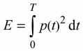 | N/A | |
| 3.3.19.4 | sound exposure level, SEL logarithmic measure of sound exposure relative toa reference value, E0 , typically the 1 kHz threshold of hearing in humans. Note 1 to entry: SEL is measured as A-weighted levels in dB. | N/A | |
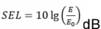 | |||
| Note 2 to entry: See B.4 of EN 50332-3:2017 for additional information. | |||
| 3.3.19.5 | digital signal level relative to full scale, dBFS levels reported in dBFS are always r. m.s. Full scale level, 0 dBFS, is the level of a dc-free 997-Hz sine wave whose undithered positive peak value is positive digital full scale, leaving the code corresponding to negative digital full scale unused Note 1 to entry: It is invalid to use dBFS for non-r. m.s. levels. Because the definition of full scale is based on a sine wave, the level of signals with a crest factor lower than that of a sine wave may exceed 0 dBFS. In particular, square wave signals may reach +3,01 dBFS. | N/A | |
| 2 | Modification to Clause 10 | -- | |
| 10.6 | Safeguards against acoustic energy sources Replace 10.6 of IEC 62368-1 with the following: | N/A | |
| 10.6.1.1 | Introduction Safeguard requirements for protection against long-term exposure to excessive sound pressure | N/A |
| levels from personal music players closely coupled to the ear are specified below. Requirements for earphones and headphones intended for use with personal music players are also covered. A personal music player is a portable equipment intended for use by an ordinary person , that: – is designed to allow the user to listen to audio or audiovisual content / material; and – uses a listening device, such as headphones or earphones that can be worn in or on or around the ears; and – has a player that can be body worn (of a size suitable to be carried in a clothing pocket) and is intended for the user to walk around with while in continuous use (for example, on a street, in a subway, at an airport, etc. ) . EXAMPLES Portable CD players, MP3 audio players, mobile phones with MP3 type features, PDAs or similar equipment. Personal music players shall comply with the requirements of either 10.6.2 or 10.6.3. NOTE 1 Protection against acoustic energy sources from telecom applications is referenced to ITU-T P.360. NOTE 2 It is the intention of the Committee to allow the alternative methods for now, but to only use the dose measurement method as given in 10.6.5 in future. Therefore, manufacturers are encouraged to implement 10.6.5 as soon as possible. Listening devices sold separately shall comply with the requirements of 10.6.6. These requirements are valid for music or video mode only. The requirements do not apply to: – professional equipment; NOTE 3 Professional equipment is equipment sold through special sales channels. All products sold through normal electronics stores are considered not to be professional equipment. – hearing aid equipment and other devices for assistive listening; – the following type of analogue personal music players: • long distance radio receiver (for example, amultiband radio receiver or world band radio receiver, an AM radio receiver), and • cassette player/recorder; NOTE 4 This exemption has been allowed because this technology is falling out of use and it is expected that within a few years it will no longer exist. This exemption will not be extended to other technologies. |
|---|
| – a player while connected to an external amplifier that does not allow the user to walk around while in use. For equipment that is clearly designed or intended primarily for use by children, the limits of the relevant toy standards may apply. The relevant requirements are given in EN 71-1:2011, 4.20 and the related tests methods and measurement distances apply. | |||
|---|---|---|---|
| 10.6.1.2 | Non.ionizing radiation from radio frequencies in the range 0 to 300 GHz The amount of non-ionizing radiation is regulated by European Council Recommendation 1999/519/EC of 12 July 1999 on the limitation of exposure of the general public to electromagnetic fields (0 Hz to 300 GHz) . For intentional radiators, ICNIRP guidelines should be taken into account for Limiting Exposure to Time-Varying Electric, Magnetic, and Electromagnetic Fields (up to 300 GHz) . For handheld and body mounted devices, attention is drawn to EN 50360 and EN 50566. | N/A | |
| 10.6.2 | Classification of devices without the capacity to estimate sound dose | N/A | |
| 10.6.2.1 | General This standard is transitioning from short-term based (30 s) requirements to long-term based (40 hour) requirements. These clauses remain in effect only for devices that do not comply with sound dose estimation as stipulated in EN 50332-3. For classifying the acoustic output LAeq , T , measurements are based on the A-weighted equivalent sound pressure level over a 30 s period. For music where the average sound pressure (long term LAeq, T) measured over the duration of the song is lower than the average produced by the programme simulation noise, measurements maybe done over the duration of the complete song. In this case, T becomes the duration of the song. NOTE Classical music, acoustic music and broadcast typically has an average sound pressure (long term LAeq, T) which is much lower than the average programme simulation noise. Therefore, if the player is capable to analyse the content and compare it with the programme simulation noise, the warning does not need to be given as long as the average sound pressure of the song does not exceed the required limit. For example, if the player is set with the programme simulation noise to 85 dB, but the average music level of the song is only | N/A |
| 65 dB, there is no need to give a warning or ask an acknowledgement as long as the average sound level of the song is not above the basic limit of 85 dB. | |||
|---|---|---|---|
| 10.6.2.2 | RS1 limits (to be superseded, see 10.6.3.2) RS1 is a class 1 acoustic energy source that does not exceed the following: – for equipment provided as a package (player with its listening device), and with a proprietary connector between the player and its listening device, or where the combination of player and listening device is known by other means such as setting or automatic detection, the LAeq, T acoustic output shall be ≤ 85 dB when playing the fixed“programme simulation noise” described in EN 50332-1. – for equipment provided with a standardized connector (for example, a 3,5 phone jack) that allows connection to a listening device for general use, the unweighted r.m.s. output voltage shall be ≤ 27 mV (analogue interface) or-25 dBFS (digital interface) when playing the fixed “programme simulation noise” described in EN 50332-1. – The RS1 limits will be updated for all devices as per 10.6.3.2. | N/A | |
| 10.6.2.3 | RS2 limits (to be superseded, see 10.6.3.3) RS2 is a class 2 acoustic energy source that does not exceed the following: – for equipment provided as a package (player with its listening device), and with a proprietary connector between the player and its listening device, or when the combination of player and listening device is known by other means such as setting or automatic 130 detection, the LAeq, T acoustic output shall be ≤ 100 dB(A) when playing the fixed “programme simulation noise” as described in EN 50332-1. – for equipment provided with a standardized connector (for example, a 3,5 phone jack) that allows connection to a listening device for general use, the unweighted r.m.s. output voltage shall be ≤ 150 mV (analogue interface) or-10 dBFS (digital interface) when playing the fixed “programme simulation noise” as described in EN 50332-1. | N/A | |
| 10.6.2.4 | RS3 limits RS3 is a class 3 acoustic energy source that exceeds RS2 limits. | N/A | |
| 10.6.3 | Classification of devices (new) | N/A | |
| 10.6.3.1 | General Previous limits (10 .6.2) created abundant false | N/A |
| negative and false positive PMP sound level warnings. New limits, compliant with The Commission Decision of 23 June 2009, are given below. | |||
|---|---|---|---|
| 10.6.3.2 | RS1 limits (new) RS1 is a class 1 acoustic energy source that does not exceed the following: – for equipment provided as a package (player with its listening device), and with a proprietary connector between the player and its listening device, or where the combination of player and listening device is known by other means such as setting or automatic detection, the LAeq, T acoustic output shall be ≤ 80 dB when playing the fixed“programme simulation noise” described in EN 50332-1. – for equipment provided with a standardized connector (for example, a 3,5 phone jack) that allows connection to a listening device for general use, the unweighted r.m.s. output voltage shall be ≤ 15 mV (analogue interface) or-30 dBFS (digital interface) when playing the fixed “programme simulation noise” described in EN 50332-1. | N/A | |
| 10.6.3.3 | RS2 limits (new) RS2 is a class 2 acoustic energy source that does not exceed the following: – for equipment provided as a package (player with its listening device), and with a proprietary connector between the player and its listening device, or where the combination of player and listening device is known by other means such as setting or automatic detection, the weekly sound exposure level, as described in EN 50332-3, shall be ≤ 80 dB when playing the fixed "programme simulation noise" described in EN 50332-1. – for equipment provided with a standardized connector (for example, a 3,5 phone jack) that allows connection to a listening device for general use, the unweighted r.m.s. output level, integrated over one week, as described in EN50332-3, shall be ≤ 15 mV (analogue interface) or-30 dBFS (digital interface) when playing the fixed“programme simulation noise” described in EN 50332-1. | N/A | |
| 10.6.4 | Requirements for maximum sound exposure | N/A | |
| 10.6.4.1 | Measurement methods All volume controls shall be turned to maximum during tests. Measurements shall be made in accordance with | N/A |
| EN 50332-1 or EN 50332-2 as applicable. | |||
|---|---|---|---|
| 10.6.4.2 | Protection of persons Except as given below, protection requirements for parts accessible to ordinary persons , instructed persons and skilled persons are given in 4.3. NOTE 1 Volume control is not considered a safeguard. Between RS2 and an ordinary person , the basic safeguard may be replaced by an instructional safeguard in accordance with Clause F.5, except that the instructional safeguard shall be placedon the equipment, or on the packaging, or in the instruction manual. Alternatively, the instructional safeguard may be given through the equipment display during use. The elements of the instructional safeguard shall be as follows: – element 1a: the symbol , IEC 60417-6044 (2011-01) – element 2: “High sound pressure” or equivalent wording – element 3: “Hearing damage risk” or equivalent wording – element 4: “Do not listen at high volume levels for long periods.” or equivalent wording An equipment safeguard shall prevent exposure of an ordinary person to an RS2 source without intentional physical action from the ordinary person and shall automatically return to an output level not exceeding what is specified for an RS1 source when the power is switched off. The equipment shall provide a means to actively inform the user of the increased sound level when the equipment is operated with an output exceeding RS1 . Any means used shall be acknowledged by the user before activating a mode of operation which allows for an output exceeding RS1 . The acknowledgement does not need to be repeated more than once every 20 h of cumulative listening time. NOTE 2 Examples of means include visual or audible signals. Action from the user is always needed. NOTE 3 The 20 h listening time is the accumulative listening time, independent of how often and how long the personal music player has been switched off. A skilled person shall not be unintentionally | N/A |
| exposed to RS3 . | |||
|---|---|---|---|
| 10.6.5 | Requirements for dose.based systems | N/A | |
| 10.6.5.1 | General requirements Personal music players shall give the warnings as provided below when tested according to EN 50332-3, using the limits from this clause. The manufacturer may offer optional settings to allow the users to modify when and how they wish to receive the notifications and warnings to promote a better user experience without defeating the safeguards. This allows the users to be informed in a method that best meets their physical capabilities and device usage needs. If such optional settings are offered, an administrator (for example, parental restrictions, business/educational administrators, etc. ) shall be able to lock any optional settings into a specific configuration. The personal music player shall be supplied with easy to understand explanation to the user of the dose management system, the risks involved, and how to use the system safely. The user shall be made aware that other sources may significantly contribute to their sound exposure, for example work, transportation, concerts, clubs, cinema, car races, etc. | N/A | |
| 10.6.5.2 | Dose.based warning and requirements When a dose of 100 % CSD is reached, and at least at every 100 % further increase of CSD , the device shall warn the user and require an acknowledgement. In case the user does not acknowledge, the output level shall automatically decrease to compliance with class RS1 . The warning shall at least clearly indicate that listening above 100 % CSD leads to the risk of hearing damage or loss. | N/A | |
| 10.6.5.3 | Exposure.based requirements With only dose-based requirements, cause and effect could be far separated in time, defying the purpose of educating users about safe listening practice. In addition to dose-based requirements, a PMP shall therefore also put a limit to the shortterm sound level a user can listen at. The exposure-based limiter (EL) shall automatically reduce the sound level not to exceed 100 dB(A) or 150 mV integrated over the past 180 s, based on | N/A |
| methodology defined in EN 50332-3. The EL settling time (time from starting level reduction to reaching target output) shall be 10 s or faster. Test of EL functionality is conducted according to EN 50332-3, using the limits from this clause. For equipment provided as a package (player with its listening device), the level integrated over 180 s shall be 100 dB or lower. For equipment provided with a standardized connector, the unweighted level integrated over 180 s shall be no more than 150 mV for an analogue interface and no more than-10 dBFS for a digital interface. NOTE In case the source is known not to be music (or test signal), the EL may be disabled. |
|---|
| 10.6.6 | Requirements for listening devices (headphones, earphones, etc.) | N/A | |
|---|---|---|---|
| 10.6.6.1 | Corded listening devices with analogue input With 94 dB LAeq acoustic pressure output of the listening device, and with the volume and sound settings in the listening device (for example, built-in volume level control, additional sound features like equalization, etc. ) set to the combination of positions that maximize the measured acoustic output, the input voltage of the listening device when playing the fixed “programme simulation noise” as described in EN 50332-1 shall be ≥ 75 mV. NOTE The values of 94 dB and 75 mV correspond with 85 dBand 27 mV or 100 dB and 150 mV. | N/A | |
| 10.6.6.2 | Corded listening devices with digital input With any playing device playing the fixed“programme simulation noise” described in EN 50332-1, and with the volume and sound settings in the listening device (for example, built-in volume level control, additional sound features like equalization, etc. ) set to the combination of positions that maximize the measured acoustic output, the LAeq, T acoustic output of the listening device shall be ≤ 100 dB with an input signal of-10 dBFS. | N/A | |
| 10.6.6.3 | Cordless listening devices In cordless mode, – with any playing and transmitting device playing the fixed programme simulation noise described in EN 50332-1; and – respecting the cordless transmission standards, where an air interface standard exists that specifies | N/A |
| the equivalent acoustic level; and – with volume and sound settings in the receiving device (for example, built-in volume level control, additional sound features like equalization, etc. ) set to the combination of positions that maximize the measured acoustic output for the above mentioned programme simulation noise, the LAeq, T acoustic output of the listening device shall be ≤ 100 dB with an input signal of-10 dBFS. | |||
|---|---|---|---|
| 10.6.6.4 | Measurement method Measurements shall be made in accordance with EN 50332-2 as applicable. | N/A |
| 3 | Modification to the whole document | -- | ||
|---|---|---|---|---|
Delete all the “country” notes in the reference document according to the following list: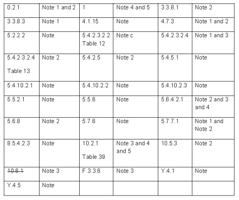 | P | |||
| 4 | Modification to Clause 1 | -- | ||
| 1 | Add the following note: NOTE Z1 The use of certain substances in electrical and electronic equipment is restricted within the EU: see Directive 2011/65/EU. | N/A | ||
| 5 | Modification to 4.Z1 | -- | ||
| 4.Z1 | Add the following new subclause after 4. 9: To protect against excessive current, short-circuitsand earth faults in circuits connected to an a.c. mains, protective devices shall be included either as integral parts of the equipment or as parts of the building installation, subject to the following, a), b) and c): a) except as detailed in b) and c), protective devices necessary to comply with the requirements of B.3.1 and B.4 shall be included as parts of the equipment; b) for components in series with the mains input to the equipment such as the supply cord, appliance coupler, [r.f.i. fi](r.f.i. fi)lter and switch, short-circuit and earth | N/A |
| fault protection may be provided by protective devices in the building installation; c) it is permitted for pluggable equipment type Bor permanently connected equipment , to rely on dedicated overcurrent and short-circuit protection in the building installation, provided that the means of protection, e.g. fuses or circuit breakers, is fully specified in the installation instructions. If reliance is placed on protection in the building installation, the installation instructions shall so state, except that for pluggable equipment type A the building installation shall be regarded as providing protection in accordance with the rating of the wall socket outlet. | |||
|---|---|---|---|
| 6 | Modification to 5.4.2.3.2.4 | -- | |
| 5.4.2.3.2.4 | Add the following to the end of this subclause: The requirement for interconnection with external circuit is in addition given in EN 50491-3:2009 . | N/A | |
| 7 | Modification to 10.2.1 | -- | |
| 10.2.1 | Add the following to c) and d) in table 39: For additional requirements, see 10.5.1. | N/A | |
| 8 | Modification to 10.5.1 | -- | |
| 10.5.1 | Add the following after the first paragraph: For RS 1 compliance is checked by measurement under the following conditions: In addition to the normal operating conditions, all controls adjustable from the outside by hand, by any object such as a tool or a coin, and those internal adjustments or pre-sets which are not locked in a reliable manner, are adjusted so as to give maximum radiation whilst maintaining an intelligible picture for 1 h, at the end of which the measurement is made. NOTE Z1 Soldered joints and paint lockings are examples of adequate locking. The dose-rate is determined by means of a radiation monitor with an effective area of 10 cm², at any point 10 cm from the outer surface of the apparatus. Moreover, the measurement shall be made under fault conditions causing an increase of the high voltage, provided an intelligible picture is maintained for 1 h, at the end of which the measurement is made. | N/A |
| For RS1, the dose-rate shall not exceed 1 μSv/h taking account of the background level. NOTE Z2 These values appear in Directive 96/29/Euratom of 13 May 1996. | |||
|---|---|---|---|
| 9 | Modification to G.7.1 | -- | |
| G.7.1 | Add the following note: NOTE Z1 The harmonized code designations corresponding to the IEC cord types are given in Annex ZD. | N/A | |
| 10 | Modification to Bibliography | -- | |
| Add the following notes for the standards indicated: | N/A | ||
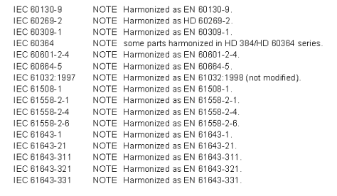 | |||
| 11 | ADDITION OF ANNEXES | -- | |
| ZB | ANNEX ZB, SPECIAL NATIONAL CONDITIONS (EN) | N/A |
| 4.1.15 | Denmark, Finland, Norway and Sweden To the end of the subclause the following is added: Class I pluggable equipment type A intended for connection to other equipment or a network shall, if safety relies on connection to reliable earthing or if surge suppressors are connected between the network terminals and accessible parts, have a marking stating that the equipment shall be connected to an earthed mains socket-outlet. The marking text in the applicable countries shall be as follows: In Denmark: “Apparatets stikprop skal tilsluttes enstikkontakt med jord som giver forbindelse til stikproppens jord.” In Finland: "Laite on liitettävä suojakoskettimilla varustettuun pistorasiaan" In Norway: “Apparatet må tilkoples jordetstikkontakt” In Sweden: “Apparaten skall anslutas till jordat uttag” | N/A | |
|---|---|---|---|
| 4.7.3 | United Kingdom To the end of the subclause the following is added: The torque test is performed using a socket-outlet complying with BS 1363, and the plug part shall be assessed to the relevant clauses of BS 1363. Also see Annex G.4.2 of this annex | N/A | |
| 5.2.2.2 | Denmark After the 2nd paragraph add the following: A warning (marking safeguard) for high touch current is required if the touch current exceeds the limits of 3,5 mA a.c. or 10 mA d.c. | N/A | |
| 5.4.11.1and Annex G | Finland and Sweden To the end of the subclause the following is added: For separation of the telecommunication network from earth the following is applicable: If this insulation is solid, including insulation forming part of a component, it shall at least consist of either • two layers of thin sheet material, each of which shall pass the electric strength test below, or • one layer having a distance through insulation of | N/A |
| at least 0,4 mm, which shall pass the electric strength test below. If this insulation forms part of a semiconductor component ([e.g. an](e.g. an) optocoupler), there is no distance through insulation requirement for the insulation consisting of an insulating compound completely filling the casing, so that clearances and creepage distances do not exist, if the component passes the electric strength test in accordance with the compliance clause below and in addition • passes the tests and inspection criteria of 5.4.8 with an electric strength test of 1,5 kV multiplied by 1,6 (the electric strength test of 5.4.9 shall be performed using 1,5 kV), and • is subject to routine testing for electric strength during manufacturing, using a test voltage of 1,5 kV. It is permitted to bridge this insulation with a capacitor complying with EN 60384-14:2005, subclass Y2 . A capacitor classified Y3 according to EN 60384- 14:2005, may bridge this insulation under the following conditions: • the insulation requirements are satisfied by having a capacitor classified Y3 as defined by EN 60384-14, which in addition to the Y3 testing, is tested with an impulse test of 2,5 kV defined in 5.4. 11; • the additional testing shall be performed on all the test specimens as described in EN 60384- 14; the impulse test of 2,5 kV is to be performed before the endurance test in EN 60384-14, in the sequence of tests as described in EN 60384-14. | |||
|---|---|---|---|
| 5.5.2.1 | Norway After the 3rd paragraph the following is added: Due to the IT power system used, capacitors are required to be rated for the applicable line-to-line voltage (230 V) . | N/A |
| 5.5.6 | Finland, Norway and Sweden To the end of the subclause the following is added: Resistors used as basic safeguard or bridging basic insulation in class I pluggable equipment type A shall comply with G.10.1 and the test of G.10.2. | N/A | |
|---|---|---|---|
| 5.6.1 | Denmark Add to the end of the subclause Due to many existing installations where the socket-outlets can be protected with fuses with higher rating than the rating of the socketoutlets the protection for pluggable equipment type A shall be an integral part of the equipment. Justification: In Denmark an existing 13 A socket outlet can be protected by a 20 A fuse. | N/A | |
| 5.6.4.2.1 | Ireland and United Kingdom After the indent for pluggable equipment type A , the following is added: – the protective current rating is taken to be 13 A, this being the largest rating of fuse used in the mains plug. | N/A | |
| 5.6.4.2.1 | France After the indent for pluggable equipment type A , the following is added: – in certain cases, the protective current rating of the circuit supplied from the mains is taken as 20 A instead of 16 A. | N/A | |
| 5.6.5.1 | To the second paragraph the following is added: The range of conductor sizes of flexible cords to be accepted by terminals for equipment with a rated current over 10 A and up to and including 13 A is: 1,25 mm2 to 1,5 mm2 in cross-sectional area. | N/A | |
| 5.6.8 | Norway To the end of the subclause the following is added: Equipment connected with an earthed mains plug is classified as class I equipment. See the Norway marking requirement in 4.1.15. The symbol IEC 60417-6092, as specified in F.3.6.2, is accepted. | N/A | |
| 5.7.6 | Denmark To the end of the subclause the following is added: The installation instruction shall be affixed to the equipment if the protective conductor current | N/A |
| exceeds the limits of 3,5 mA a.c. or 10 mA d.c. | |||
|---|---|---|---|
| 5.7.6.2 | Denmark To the end of the subclause the following is added: The warning (marking safeguard) for high touch current is required if the touch current or the protective current exceed the limits of 3,5 mA . | N/A | |
| 5.7.7.1 | Norway and Sweden To the end of the subclause the following is added: The screen of the television distribution system is normally not earthed at the entrance of the building and there is normally no equipotential bonding system within the building. Therefore the protective earthing of the building installation needs to be isolated from the screen of a cable distribution system. It is however accepted to provide the insulation external to the equipment by an adapter or an interconnection cable with galvanic isolator, which may be provided by a retailer, for example. The user manual shall then have the following or similar information in Norwegian and Swedish language respectively, depending on in what country the equipment is intended to be used in: “Apparatus connected to the protective earthing of the building installation through the mains connection or through other apparatus with a connection to protective earthing – and to a television distribution system using coaxial cable, may in some circumstances create a fire hazard. Connection to a television distribution system therefore has to be provided through a device providing electrical isolation below a certain frequency range (galvanic isolator, see EN 60728- 11)” NOTE In Norway, due to regulation for CATV-installations, and in Sweden, a galvanic isolator shall provide electrical insulation below 5 MHz. The insulation shall withstand a dielectric strength of 1,5 kV r. m.s. , 50 Hz or 60 Hz, for 1 min. Translation to Norwegian (the Swedish text will also be accepted in Norway): “Apparater som er koplet til beskyttelsesjord via nettplugg og/eller via annet jordtilkoplet utstyr – og er tilkoplet et koaksialbasert kabel-TV nett, kan forårsake brannfare. For å unngå dette skal det ved tilkopling avapparater til kabel-TV nett installeres en galvanisk isolator mellom apparatet og kabel-TV | N/A |
| nettet.” Translation to Swedish: ”Apparater som är kopplad till skyddsjord via jordatvägguttag och/eller via annan utrustning ochsamtidigt är kopplad till kabel-TV nät kan i vissa fall medfőra risk főr brand. Főr att undvika detta skall vid anslutning av apparaten till kabel-TV nätgalvanisk isolator finnas mellan apparaten och kabel-TV nätet.”. | |||
|---|---|---|---|
| 8.5.4.2.3 | United Kingdom Add the following after the 2nd dash bullet in 3rd paragraph: An emergency stop system complying with the requirements of IEC 60204-1 and ISO 13850 is required where there is a risk of personal injury. | N/A | |
| B.3.1 and B.4 | Ireland and United Kingdom The following is applicable: To protect against excessive currents and shortcircuits in the primary circuit of direct plug-in equipment , tests according to Annexes B.3.1 and B.4 shall be conducted using an external miniature circuit breaker complying with EN 60898-1, Type B, rated 32A. If the equipment does not pass these tests, suitable protective devices shall be included as an integral part of the direct plug-in equipment , until the requirements of Annexes B.3.1 and B.4 are met | N/A | |
| G.4.2 | Denmark To the end of the subclause the following is added: Supply cords of single phase appliances having a rated current not exceeding 13 A shall be provided with a plug according to DS 60884-2-D1:2011 . CLASS I EQUIPMENT provided with socket-outlets with earth contacts or which are intended to be used in locations where protection against indirect contact is required according to the wiring rules shall be provided with a plug in accordance with standard sheet DK 2-1a or DK 2-5a. If a single-phase equipment having a RATED CURRENT exceeding 13 A or if a polyphase equipment is provided with a supply cord with a plug, this plug shall be in accordance with the standard sheets DK 6-1a in DS 60884-2-D1 or EN 60309-2. | N/A |
| Mains socket outlets intended for providing power to Class II apparatus with a rated current of 2,5 Ashall be in accordance DS 60884-2-D1:2011 standard sheet DKA 1-4a. Other current rating socket outlets shall be in compliance with Standard Sheet DKA 1-3a or DKA 1-1c. Mains socket-outlets with earth shall be in compliance with DS 60884-2-D1:2011 Standard Sheet DK 1-3a, DK 1-1c, DK1-1d, DK 1- 5a or DK 1-7a Justification: Heavy Current Regulations, Section 6c | |||
|---|---|---|---|
| G.4.2 | United Kingdom To the end of the subclause the following is added: The plug part of direct plug-in equipment shall be assessed to BS 1363: Part 1, 12. 1, 12.2, 12.3, 12.9, 12. 11, 12. 12, 12. 13, 12. 16, and 12. 17, except that the test of 12.17 is performed at not less than 125 °C. Where the metal earth pin is replaced by an Insulated Shutter Opening Device (ISOD), the requirements of clauses 22.2 and 23 also apply. | N/A | |
| G.7.1 | United Kingdom To the first paragraph the following is added: Equipment which is fitted with a flexible cable or cord and is designed to be connected to a mains socket conforming to BS 1363 by means of that flexible cable or cord shall be fitted with a ‘standard plug’ in accordance with the Plugs and Sockets etc.(Safety) Regulations 1994, Statutory Instrument 1994 No. 1768, unless exempted by those regulations. NOTE "Standard plug" is defined in SI 1768:1994 and essentially means an approved plug conforming to BS 1363 or an approved conversion plug. | N/A | |
| G.7.1 | Ireland To the first paragraph the following is added: Apparatus which is fitted with a flexible cable or cord shall be provided with a plug in accordance with Statutory Instrument 525: 1997,“13 A Plugsand Conversion Adapters for Domestic Use Regulations: 1997. S. I. 525 provides for the recognition of a standard of another Member State which is equivalent to the relevant Irish Standard | N/A |
| G.7.2 | Ireland and United Kingdom To the first paragraph the following is added: A power supply cord with a conductor of 1,25 mm2 is allowed for equipment which is rated over 10 A and up to and including 13 A. | N/A |
|---|
| ZC | ANNEX ZC, NATIONAL DEVIATIONS (EN) | N/A | |
|---|---|---|---|
| 10.5.2 | Germany The following requirement applies: For the operation of any cathode ray tube intended for the display of visual images operating at an acceleration voltage exceeding 40 kV, authorization is required, or application of type approval (Bauartzulassung) and marking. Justification: German ministerial decree against ionizing radiation (Röntgenverordnung), in force since 2002-07-01, implementing the European Directive 96/29/EURATOM. NOTE Contact address: Physikalisch-Technische Bundesanstalt, Bundesallee 100, D- 38116 Braunschweig, Tel.: Int+49-531-592-6320, Internet: http://www.ptb.de | N/A |
| ZD | IEC and CENELEC CODE DESIGNATIONS FOR FLEXIBLE CORDS (EN) | N/A |
|---|---|---|
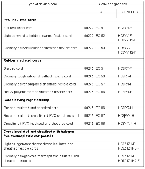 | N/A |
Notes: Before placing the products in the different countries, the manufacturer must ensure that:
- Operating Instructions, Ratings Labels and Warnings Labels written in an Accepted or Official Language of the county in question.
- The equipment complies with the National Standards and/or Electrical Codes of the country in question.
National and Group Differences for IEC 62368-1:2018 (Third Edition) as per CB Bulletin
| National Differences covered by this report | |||||
|---|---|---|---|---|---|
| Country | CENELEC Group differ. (see separate attachment) | National differ. | Base standard | National standard | Tested |
| AR Argentina | - | Yes | IEC 62368-1 ed3 | - | Yes |
| AU Australia | - | Yes | IEC 62368-1 ed3 | AS/NZS 62368. 1:2022 | Yes |
| AT Austria | Yes | - | IEC 62368-1 ed3 | - | Yes |
| BY Belarus | - | - | IEC 62368-1 ed3 | - | Yes |
| BE Belgium | Yes | - | IEC 62368-1 ed3 | - | Yes |
| CA Canada | - | Yes | IEC 62368-1 ed3 | CSA/UL 62368-1:2019 | Yes |
| CH Switzerland | Yes | - | IEC 62368-1 ed3 | - | Yes |
| CN China | - | - | IEC 62368-1 ed3 | GB 4943.1-2022 | Yes |
| DE Germany | Yes | - | IEC 62368-1 ed3 | EN IEC 62368- 1:2020+A11:2020 | Yes |
| DK Denmark | Yes | - | IEC 62368-1 ed3 | DS/EN IEC 62368- 1:2020+A11:2020 | Yes |
| FI Finland | Yes | - | IEC 62368-1 ed3 | - | Yes |
| FR France | Yes | - | IEC 62368-1 ed3 | EN IEC 62368- 1:2020+A11:2020 | Yes |
| GB United Kingdom | Yes | - | IEC 62368-1 ed3 | - | Yes |
| HU Hungary | Yes | - | IEC 62368-1 ed3 | - | Yes |
| IT Italy | Yes | - | IEC 62368-1 ed3 | - | Yes |
| IL Israel | - | - | IEC 62368-1 ed3 | - | Yes |
| JP Japan | - | - | IEC 62368-1 ed3 | J62368-1(2023) , J3000(H25) | Yes |
| KR Korea | - | Yes | IEC 62368-1 ed3 | KC 62368-1(2021-08) | Yes |
| MY Malaysia | - | - | IEC 62368-1 ed3 | - | Yes |
| NO Norway | Yes | - | IEC 62368-1 ed3 | - | Yes |
| NL Netherlands | Yes | - | IEC 62368-1 ed3 | - | Yes |
| NZ New Zealand | - | Yes | IEC 62368-1 ed3 | AS/NZS 62368. 1:2022 | Yes |
| SA Saudi Arabia | - | Yes | IEC 62368-1 ed3 | SASO-IEC-62368-1:2020 | Yes |
| SE Sweden | Yes | - | IEC 62368-1 ed3 | - | Yes |
| SG Singapore | - | Yes | IEC 62368-1 ed3 | - | Yes |
| SI Slovenia | Yes | - | IEC 62368-1 ed3 | - | Yes |
| UA Ukraine | - | - | IEC 62368-1 ed3 | - | Yes |
| US United States of America | - | Yes | IEC 62368-1 ed3 | CSA/UL 62368-1:2019 | Yes |
| General remarks: The test results presented in this report relate only to the object tested. This report shall not be reproduced, except in full, without the written approval of the Issuing testing laboratory. Throughout this report a point is used as the decimal separator. See attachment 1 for European Group Differences and National Differences. Notes: Before placing the products in the different countries, the manufacturer must ensure that: 1. Operating Instructions, Ratings Labels and Warnings Labels written in an Accepted or Official Language of the county in question. 2. The equipment complies with the National Standards and/or Electrical Codes of the country in question. |
|---|
| Possible test case verdicts: -test case does not apply to the test object .................: N/A -test object does meet the requirement .......................: P (Pass) -test object does not meet the requirement .................: F (Fail) |
| AR Argentina AR | |||
|---|---|---|---|
| Ratings shall cover 220 Vac-50 Hz | Not directly connected to mains | N/A | |
| Class 0 and Class 0I appliances are not allowed | N/A | ||
| Safety instructions and manuals shall be written in Spanish language (Resolution 92/98) | Should be evaluated during the national approval | N/A | |
| Country of origin shall be shown on the marking plate or, if not possible, in the primary packaging (Resolution 92/98) | Should be evaluated during the national approval | N/A | |
| Address of the importer in Argentina shall be shown on the product or on the primary packaging (Resolution 92/98) | Should be evaluated during the national approval | N/A | |
| Class I appliances provided with plugs shall be provided with the label specified in sheet "Class I"(Disposition 731/87) | N/A | ||
| Class II appliances provided with plugs shall be provided with the label specified in sheet "Class II"(Disposition 731/87) | N/A | ||
| Plugs shall be in conformity with IRAM 2063 Standard for Class II appliances and IRAM 2073 Standard for Class I appliances (Resolution 524/98) | N/A | ||
| Adaptors/Transformers provided with integrated plugs shall be provided with blades which shall meet the geometry of IRAM 2063 standard for Class II appliances or IRAM 2073 standard for Class I appliances (Resolution 524/98) | N/A | ||
| Appliances certified under System Nº4 (Type Certification scheme) shall be marked with the symbol specified in sheet "St Mark" (Resolution 197/04) | N/A | ||
| Appliances certified under System Nº5 (Mark of Conformity Certification scheme) shall be marked with the symbols specified in sheet "S Mark"(Resolution 799/99) | N/A |
| ATTACHMENT TO TEST REPORT IEC 62368-1 (AUSTRALIA / NEW ZEALAND) NATIONAL DIFFERENCES (Audio/video, information and communication technology equipment) | |||
|---|---|---|---|
| Differences according to ............... : AS/NZS 62368. 1:2022 | |||
| TRF template used:.......................... : IECEE OD-2020-F3, Ed. 1.1 | |||
| Attachment Form No..................... : AU_NZ_ND_IEC62368_ 1E Attachment Originator................... : JAS-ANZ Master Attachment......................... : 2022-07-01 | |||
| Copyright © 2020 IEC System for Conformity Testing and Certification of Electrical Equipment (IECEE), Geneva, Switzerland. All rights reserved. | |||
| National Differences | -- | ||
| Appendix ZZ | Variations to IEC 62368-1:2018 (ED. 3.0) for Australia and New Zealand | N/A | |
| ZZ1 Scope | This Appendix lists the normative variations to IEC 62368-1:2018 (ED. 3.0) | N/A | |
| ZZ2 Variations | The following modifications are required for Australian/New Zealand conditions: | N/A | |
| 2 | After the first paragraph, add the following: The Australian or Australian/New Zealand Standards listed below are modified adoptions of, or not equivalent to, the IEC normative references and are required for the application of this Standard. All references in the source text to those IEC normative references shall be replaced by references to the corresponding Australian or Australian/New Zealand Standards. Australian or Australian/New Zealand Standards that are identical adoptions of international normative references may be used interchangeably -AS/NZS 3112, Approval and test specification—Plugs and socket-outlets -AS/NZS 3123, Approval and test specification—Plugs, socket-outlets and couplers for general industrial application -AS/NZS 3191, Electric flexible cords -AS/NZS 60884.1.Plugs and socket-outlets for household and similar purposes, Part 1: General requirements -IEC 60086-2 Primary batteries—Part 2: Physical and electrical specifications -AS/NZS 60065, Audio, video and similar electronic apparatus—Safety requirements (IEC 60065:2015 (ED.8. 0) MOD) -AS/NZS 60320. 1, Appliance couplers for household and similar general purposes, Part 1: General requirements (IEC 60320-1, Ed.2.1 (2007) MOD) | N/A |
| -AS/NZS 60320.2.2, Appliance couplers for household and similar general purposes Part 2.2: Interconnection couplers for household and similar equipment (IEC 60320-2- 2, Ed.2. 0 (1998) MOD) -AS/NZS 60695.2.11, Fire hazard testing, Part 2. 11: Glowing/hot wire based test methods—Glowwire flammability test method for end-products -AS/NZS 60695.11.5, Fire hazard testing, Part 11. 5: Test flames—Needle-flame test method—Apparatus, confirmatory test arrangement and guidance -AS/NZS 60695.11. 10, Fire hazard testing, Part 11. 10: Test flames—50 W horizontal and vertical flame test methods -AS/NZS 60884. 1, Plugs and socket-outlets for household and similar purposes, Part 1: General requirements -AS/NZS 60950. 1, Information technology equipment—Safety, Part 1: General requirements (IEC 60950-1, Ed.2.2 (2013), MOD) IEC 61032:1997, Protection of persons and equipment by enclosures—Probes for verification -AS/NZS 61558. 1, Safety of Power Transformers, Power Supplies, Reactors and Similar Products, Part 1: General requirements and tests (IEC 61558-1 Ed 3, MOD) -AS/NZS 61558.2. 16, Safety of transformers, reactors, power supply units and similar products for voltages up to 1 100 V, Part 2. 16: Particular requirements and tests for switch mode power supply units and transformers for switch mode power supply units. | |||
|---|---|---|---|
| 4.7.2 | Requirements Delete the text of the second paragraph and replace with the following: Equipment with a plug portion, suitable for insertion into a 10 A 3-pin flat-pin socket-outlet conforming to AS/NZS 3112, shall conform to the requirements in AS/NZS 3112 for equipment with integral pins for insertion into socket-outlets. Conformity is checked by inspection and, if necessary, by the tests in AS/NZS 3112. NOTE: Equipment with plug portions for use in countries other than Australia and New Zealand will need to conform to other countries’requirements Note Additional AS/NZS 3112 Appendix J,TRF is appended to end of this TRF. | N/A | |
| 4.7.3 | Compliance Criteria Delete this clause | N/A |
| 4.8.1 | General After second list, add the following: NOTE: Refer to the Consumer Goods (Products Containing Button/Coin Batteries) Safety Standard 2020 and Consumer Goods (Products Containing Button/Coin Batteries) Information Standard 2020 for more information on button cell batteries in Australia.. | N/A | ||||||
|---|---|---|---|---|---|---|---|---|
| 5.4.10.2.1 | General Delete the first paragraph and replace with the following: In Australia, the separation is checked by the test given in both Clause 5.4.10.2.2 and Clause 5.4.10.2.3. In New Zealand, the separation is checked by the test given in either 5.4.10.2.2 or 5.4.10.2.3.. | N/A | ||||||
| Table 28 | Delete Table 28 and replace with the following: | N/A | ||||||
| Parts | Impulse test | Steady state test | ||||||
| New Zealand Australia | New Zealand | Australia | ||||||
| Parts indicated in Clause 5.4.10.1 a) a | 2.5 kV | 7.0 kV for hand-held telephones and headsets, 2.5 kV for other equipment. | 1.5 kV | 3 kV | ||||
| Parts indicated in Clause 5.4.10.1 b) and c) b | 1.5 kV c | 1.0 kV | 1.5 kV | |||||
| a Surge suppressors shall not be removed. b Surge suppressors may be removed, provided that such devices pass the impulse test of Clause 5.4.10.2.2 when tested as components outside the equipment. c During this test, it is allowed for a surge suppressor to operate and for a sparkover to occur in a GDT. | ||||||||
| 5.4.10.2.2 | Delete “NOTE” and replace with “NOTE 1”. After NOTE 1, add the following: NOTE 2: For Australia, the 7 kV impulse simulates lightning surges on typical rural and semi-rural network lines. NOTE 3: For Australia, the value of 2.5 kV for Clause 5.4.10.1 a) was chosen to ensure the adequacy of the insulation concerned and does not necessarily simulate likely overvoltages. | N/A | ||||||
| 5.4.10.2.3 | Delete “NOTE” and replace with “NOTE 1”. After NOTE 1, add the following: NOTE 2: For Australia, where there are capacitors across the insulation under test, it is recommended that d.c. test voltages are used. NOTE 3: The 3 kV and 1.5 kV values for Australia have been determined considering the low frequency induced voltages from the power supply distribution system. | N/A | ||||||
| 6 | Electrically.caused fire | N/A |
| 6.6 | After Clause 6.6, add the new Clauses 6.201 as follows: 6.201 External power supplies, docking stations and other similar devices (see special national conditions) | N/A | |
|---|---|---|---|
| 8.6 | Stability of equipment | N/A | |
| Table 36 | Footnote a, after first sentence, add the following: Equipment having displays with moving images shall include “television sets and display devices”. | N/A | |
| 8.6.1 | After Clause 8.6.1 add the following new clauses: 8.6.201 Restraining Device fixing point (see special national conditions) 8.6.202 Restraining device (see special national conditions) | N/A | |
| Annex F Paragraph F.3.3.4 | Rated Voltage Delete “NOTE” and replace with NOTE1”After NOTE 1, add the following Equipment that is intended for connection to the supply mains in Australia and New Zealand shall be marked with: (a) A rated voltage of: • 230 V for single phase equipment • 400 V for poly phase equipment Or (b) A rated voltage range that includes: • 230 V for single phase equipment • 400 V for poly phase equipment NOTE 2: equipment that is not rated as above isnot suitable for direct connection to the supply mains in Australia or new Zealand. | N/A | |
| Annex F.3.3.5 | After the list, add the following Equipment that is intended for connection to supply mains in Australia or New Zealand shall be marked with a rated frequency of 50 Hz or a rated frequency range or nominal value which includes 50Hz | N/A | |
| Annex F.3.8 | After “The DC output of an external power supply”, insert ”or docking stations and other similar external devices” | N/A | |
| Annex G Paragraph G.4.2 | Mains connectors 1 After “lEC 60320”, insert “or AS/NZS 60320 series”. 2 After “lEC 60906-1”, insert”or AS/NZS 3123” 3 After first paragraph add the following: 10 A or 15 A 250 V flat pin plugs for the connection of equipment to mains-powered socket-outlets for household or similar general useshall comply with AS/NZS 3112 or AS/NZS 60884.1. | N/A |
| Paragraph G.5.3.1 | Transformers, General 1 Third dashed point replace ílEC 61558-1 and the relevant parts of IEC 61558-2’ with íAS/NZS 61558-1 and the relevant parts of AS/NZS 61558.2’ 2 Fourth dashed point replace ílEC 61558-2-16’with íAS/NZS 61558.2. 16’. | N/A | |
|---|---|---|---|
| Annex G.7.1 | Mains supply cords, General Fourth dashed paragraph, replace ílEC 60320-1’with íAS/NZS 60320. 1’ | N/A | |
| Table G.7 | Sizes of conductors 1 First column, second row, delete “6” and replace with “7 .5” 2 Second column, second row, delete í0,75’ and replace with í0 .75b 3 Delete NOTE 1. 4 Replace íNOTE 2’ with íNOTE:’. 5 Delete íFootnote b’ and replace with the following: b This nominal cross-sectional area is only allowed for Class II appliances if the length of the power supply cord, measured between the point where the cord, or cord guard, enters the appliance, and the entry to the plug does not exceed 2 m (0 .5 mm2 three-core supply flexible cords are not permitted; see AS/NZS 3191) . 6 Footnote c replace ílEC 60320-1’with íAS/NZS 60320.1’ 7 Footnote d replace ílEC 60320-1’with íAS/NZS 60320.1’ | N/A | |
| Annex MM 2.1 | Add “lEC 60086-2” to the list | N/A | |
| Annex M Paragraph M.3.2 | Test method Delete”NOTE” and replace with “NOTE 1”After NOTE 1 add the following: NOTE 2: In cases where the voltage source is provided by power from an unassociated power source, consideration should be given to the effects of possible single fault conditions in the unassociated equipment. If the power source is unknown then it should be assumed that the maximum limit of ES1 may be applied to the source input under assumed single fault conditions in the source when assessing the charging circuit in the equipment under test. | N/A | |
| Special national conditions (if any) | -- |
| 6.201 | External power supplies, docking stations and other similar devices For external power supplies, docking stations and other similar devices, during and after abnormal operating conditions and during single fault conditions the output voltage— (a) at all ES1 outlets or connectors shall not increase by more than 10 % of the output rated voltage under normal operating conditions, measured after 3 s of introducing a singlefault condition and after 3 s of introducing abnormal operating conditions; and (b) of a USB outlet or connector shall not increase by more than 3 V or 10 % of the output rated voltage under normal operating conditions, whichever is higher, measured after3 seconds of introducing a single fault condition and after 3 s of introducing abnormal operating conditions For equipment with multiple rated voltages at the output, the requirements apply with the equipment configured for each output rated voltage in turn NOTE: This is intended to reduce the possibility of battery fire or explosion in attached equipment or accessories when charging secondary lithium batteries. The 3 s measurement delay is based on IEC document 108/742/INF, TC 108, Standards Interpretation Panel Question 15—Output voltage, in relation to similar requirements in IEC 62368-3:2017 . Conformity shall be checked by measurement, taking into account the abnormal operating conditions of Annex B.3 and the simulated single fault conditions of Annex B.4. | N/A | |
|---|---|---|---|
| 8.6.201 | Restraining device fixing point Freestanding-capable MS2 and MS3 television sets and display devices shall be provided with a fixing point to facilitate the anchoring of the equipment from toppling The fixing point shall conform to Clause 8.7 where the fixing point uses a wall, ceiling or other structure mount. Alternatively, the fixing point shall be capable of withstanding a pull equal to the mass of the equipment in all directions without damage Instructions for installation or instructions for useshall be provided to specify correct use of the fixing point | N/A |
| 8.6.202 | Restraining device MS2 and MS3 television sets and display devices shall be provided with a restraining device and associated hardware to attach to the television set or display device. The restraining device shall be capable of withstanding a pull equal to the mass of the equipment in all directions. Instructions for installation or instructions for useshall be provided to specify correct use of the fixing point . | N/A |
|---|
| AS/NZS 3112:2017 Appendix J | |||
|---|---|---|---|
| Clause | Requirement + Test | Result-Remark | Verdict |
| ATTACHMENT TO TEST REPORT AS_NZS_ 3112:2017_+A1:2021 Appendix J AUSTRALIAN / NEW ZEALAND NATIONAL DIFFERENCES (Approval and test specification—Plugs and socket-outlets) | |||
| Differences according to ............... : AS_NZS_ 3112:2017_Amendment 1:2021_Appendix J | |||
| TRF template used:........................ : IECEE OD-2020-F3, Ed. 1.1 | |||
| Attachment Form No..................... : AS_NZS_ 3112:2017_Appendix J Attachment Originator................... : JAS-ANZ Master Attachment......................... : 2022-06 | |||
| Copyright © 2020 IEC System for Conformity Testing and Certification of Electrical Equipment (IECEE), Geneva, Switzerland. All rights reserved. | |||
| Note: AS/NZS 3112 is NOT covered by IECEE Accreditation for Testing / Reporting Please State Laboratory Accreditation for this Standard | -- | ||
| Accreditation | -- |
| J1 SCOPE | General: This Appendix specifies additional dimensional and constructional requirements for detachable plug portions, or equipment incorporating integral supply pins or equipment incorporating detachable plug portions. This Appendix shall be read in conjunction with Section 2 of this Standard. For the purposes of this Appendix, where the term ‘plug’ is used in Section 2 itshall be taken to mean the plug portion of equipment or the detachable plug portion. The equipment shall comply with the relevant product Standard. The tests and requirements specified in this Appendix are in addition to any test and requirements of the relevant product Standard for the equipment. (AS/NZS 3112:2017/A1:2021) | N/A |
|---|
| J2 | DEFINITION | N/A |
|---|---|---|
| J2.1 | Detachable plug portion A plug portion that is detachable from the equipment and with connections including the following standardized outputs and other contacts (a) Type A (see Figure J1): A detachable plug portion with a connection intended for plugging directly into equipment. The connection being via the equipment group 1 appliance inlet within the scope of AS/NZS 60320.1. (b) Type B (see Figure J2): A detachable plug portion with a non-standardized connection intended for plugging directly into equipment (c) Type C (see Figure J3): A detachable plug portion with a connection intended for use with an adaptor connected to a flexible cord so as to replicate a supply plug and flexible cord configuration. The connection being via a group 1 appliance outlet within scope of AS/NZS 60320.2.2, which is integral with the plug portion (AS/NZS 3112:2017) | N/A |
| J2.2 | Integral plug portion A plug portion that is integral to the equipment enclosure and is not detachable (AS/NZS 3112:2017) | N/A |
| J2.3 | Plug portion A plug portion is that portion of equipment with pins for insertion into a socket-outlet, including the plug pins, terminals of the plug pins, external dimensions of the‘maximum projection’ and any connections of a detachable plug portion. (AS/NZS 3112:2017/A1:2021) | N/A |
| J3 | REQUIREMENTS FOR THE PLUG PORTION | N/A | |
|---|---|---|---|
| J3.1 | General The following provisions apply to the dimensional and constructional requirements of plug portions of equipment and any detachable connection between the plug portion and the equipment: | N/A | |
| (a) | For detachable plug portions intended for connection to the equipment in multiple orientations, the relevant tests are performed in the most onerous orientation. | N/A | |
| (b) | For Type A detachable plug portion, the relevant requirements of AS/NZS 3105:2014 are applicable, in addition to conformance with relevant clauses of this Appendix | N/A | |
| (c) | For Type B detachable plug portions, the conformance is shown by the relevant clauses of this Appendix. | N/A | |
| (d) | For Type C detachable plug portions, conformance is shown by assessment to Section 2 of this Standard (plugs) and relevant clauses of this Appendix (AS/NZS 3112:2017) | N/A |
| J3.2 | Plug pins of plug portions The requirements of Clause 2.2 are applicable for plug pins. | N/A |
|---|
| 2.2 | PLUG PINS | N/A | |
|---|---|---|---|
| 2.2.1 | Current carrying parts of plug pins of metal having sufficient mechanical strength, electrical conductivity and resistance to corrosion adequate for the intended use | N/A | |
| Plug pin material? | |||
| 2.2.3 | Plug pins adequately proportioned throughout and portion adjacent to the connection designed to not introduce a stress concentration which may lead toa fracture of the pin, and suitably shaped to prevent abrasion or cutting of conductor strands due to flexure in normal use | N/A | |
| Exposed ends of plug pins have a lead-in, bevel or radius to facilitate entry into socket-outlets and to operate shutters | N/A | ||
| Flat-pins with the following profile are deemed to comply: | |||
| (a) | Flat-pins with a radius on the end with side bevels may have a width and thickness profile as specified in Figure 2 . 1(h) | N/A | |
| (b) | Flat-pins square on the end with corner and side bevels may have a width and thickness profile as specified in Figure 2 . 1(i) | N/A | |
| (c) | Flat-pins square on the end with corner bevels anda radius on the sides may have a width and thickness profile as specified in Figure 2 . 1(j) | N/A | |
| Contact portion of the pins smooth and free from openings or indentations | N/A | ||
| Flat pin plugs having a longitudinal seam or opening in the contact portion of one face; width not exceeding 0.3 mm and | N/A | ||
| Thickness not exceeding 1.58 mm | N/A | ||
| Exposed portion of earthing pins and pins other than insulated pins free from any non-metallic coverings or coatings (AS/NZS 3112:2017) | N/A | ||
| 2.2.4 | Live parts of insulated pin plugs not exposed when plug is partially or fully engaged with associated socket | N/A | |
| Compliance by measurement to Figure 2.4 | (see appended table) | N/A | |
| Lacquer, enamel or sprayed insulating coating not considered to be insulation material | N/A |
| All live pins on low voltage plugs except for those shown in Figure 2.1 (a2),(b) and (g) of the insulated pin type | N/A | ||
|---|---|---|---|
| Colour green or green / yellow not used for insulation of insulated pins (AS/NZS 3112:2017) | N/A |
| J3.3 | Ratings and dimensions for low-voltage plug portions Requirements of clauses 2.8.1 and 2.8.4 apply for rating and dimensions | N/A |
|---|
| 2.8 | Ratings and Dimensions of Low Voltage Plugs | ||
|---|---|---|---|
| 2.8.1 | Plugs with ratings up to and including 20A; shall conform to the appropriate dimensions shown in Figure 2.1 | (see appended results) | N/A |
| Rating of plug | A | ||
| Nominal dimensions covering disposition of pins checked by gauge of Appendix A | N/A | ||
| Distance between live pin and edge of moulding to not less than 9 mm | N/A | ||
| Measured distance | mm | ||
| No point on plug face protrudes more than 0.5 mm | N/A | ||
| Measured protrusion | mm | ||
| Dimensional requirements of Figure 2 . 1(e2) did not applied to plugs with greater than three pins (AS/NZS 3112:2017) | N/A | ||
| 2.8.4 | Low voltage plugs comply with dimensions of Figure 2.1 | (see appended table 2.8.1) | N/A |
| Disposition of pins checked by gauge complying with Appendix A, B or F as appropriate | N/A | ||
| Low voltage plug having rating up to 15A and of the Figure 2.1 (a1), (c), (d), (f) or (g) type; comply with dimensional requirements of Figure 2.1 (e1 and e2) | N/A | ||
| 20A plug of Figure 2.1 (a2) type complies with dimensional requirements of Figure 2.1 (e2) | N/A | ||
| Plugs with insulated pins need not comply with dimension R20 .0 ± 1 mm requirement of Figure 2.1 (e3) provided there is at least 9mm from the edge of the live pins to the edge of the plug face Figure 2 . 1(e3) . (AS/NZS 3112:2017) | N/A |
| J3.4 | Internal connections for plug portions Requirements of clause 2.9 apply for internal connections; unless | N/A |
|---|
| requirements contained in the relevant product standard (AS/NZS 3112:2017) |
|---|
| 2.9 | INTERNAL CONNECTIONS | N/A | |
|---|---|---|---|
| Plug provided with earthing connections designed and constructed so that when plug is correctly wired and assembled: | N/A | ||
| (a) | Loose terminal screw or conductive material cannot bridge any live or earthed parts | N/A | |
| (b) | Earthing parts effectively isolated from contact with live conductor which may become detached | N/A | |
| (c) | Live parts effectively isolated from contact with any earthing conductor which may become detached | N/A | |
| Any connections for auxiliary devices comply with above requirements (AS/NZS 3112:2017) | N/A |
| J3.5 | Arrangement of earthing connections for plug portions Requirements of clause 2.10 apply for arrangement of earthing connections | N/A |
|---|
| 2.10 | Arrangement of earthing connections | N/A | |
|---|---|---|---|
| Earthing pin radial to the circle embracing the pins (AS/NZS 3112:2017) | N/A |
| J3.6 | Configuration of plug portions Requirements of clause 2.12.6 apply for configuration of the plug portion (AS/NZS 3112:2017) | N/A |
|---|
| 2.12 | Marking | ||
|---|---|---|---|
| 2.12.6 | Configuration of plugs | N/A | |
| Pins disposed so that configuration, as viewed from the pins, is earth, neutral and active in a clockwise direction | N/A | ||
| Where there is no earthing pin; live pins conform to this configuration (AS/NZS 3112:2017) | N/A |
| J4 | Tests | N/A |
|---|
| J4.1 | General Plug portions of equipment shall be subjected to the following tests and unless stated otherwise, shall comply with the requirements specified in Section 2 for each test. The number of test samples shall be in accordance with Table J1 | N/A |
|---|
| For equipment with a detachable plug portion, the assessment(s) of Table J1 tests 2, 3, 5, 10 and 11 shall be conducted on the— (a) assembled equipment with the detachable plug portion connected; and (b) the detachable plug portion after it has been separated from the equipment (AS/NZS 3112:2017/A1:2021) |
|---|
| J4.2 | High voltage test The requirements of Clause 2.13.3 are applicable unless requirements are contained in the relevant product standard (AS/NZS 3112:2017) | N/A |
|---|
| 2.13.3 | Test No.1-High voltage test | N/A | |
|---|---|---|---|
| Plug withstands without failure electric strength test as specified (AS/NZS 3112:2017) | (see appended table) | N/A |
| J4.3 | Mechanical strength | N/A |
|---|---|---|
| J4.3.1 | Tumbling barrel test The tumbling barrel test is applied to determine the mechanical strength of the plug portions and equipment having integral or detachable plug portions. For equipment with a detachable plug portion, the detachable plug portion may become detached during the test. If this occurs the detachable plug portion shall be reassembled with the equipment when the pins are straightened as per (a) and (b) below. Three samples (Samples BCD in Table J1) that have not been subjected to any previous test are tested as specified in Clause 2.13.7.1 , however the test is modified as follows: | N/A |
| They are tested in a tumbling barrel as described in AS 60068.2.32 or test Free fall repeated – Procedure 2 in IEC 60068-2.31. The samples shall be dropped from a height of 500 mm onto a steel plate, 3 mm thick. The barrel shall be turned at a rate of 5 r/min, to yield 10 falls per minute. Only one sample shall be tested at a time. A sample is dropped— (a) 500 times if the mass of the specimen does not exceed 250 g. The pins being straightened after each 100 drops and at the completion of the test to pass through the appropriate gauge of Figure A1 , Figure B1 or Figure F1 ; and | N/A |
| (b) 250 times if the mass of the specimen exceeds 250 g. The pins being straightened after each 25 drops and at the completion of the test to pass through the appropriate gauge of Figures A1 , Figure B1 or Figure F1 . (AS/NZS 3112:2017/A1:2021) | |||
|---|---|---|---|
| Mass of sample | Grams | N/A | |
| Number of drops | 500 / 250 | N/A | |
| Compliance shall be checked by Paragraph J4 .3.3 | (See appended table) | N/A |
| J4.3.2 | Test No.3 Impact test. Plug portions and equipment having integral plug portions or detachable plug portions shall withstand lateral impact forces. All samples that were subjected to the tests in Paragraph J4 .3.1 (Samples BCD in Table J1) shall be tested as follows: | N/A | |
|---|---|---|---|
| (a) The sample shall be positioned at the centre of a steel plate with a thickness of at least 6 mm. Apertures in the steel plate for the plug pins to pass through shall conform to the corresponding socket Standard. The sample shall be held against the steel plate by clamping all the pins. | N/A | ||
| (b) Samples shall be subjected to blows, with an impact energy of 1.0 ± 0.05 J by any means having the same performance as the spring-operated impact-test apparatus of AS/NZS 3100. | N/A | ||
| (c) Three blows shall be applied to every point that is most likely to directly or indirectly stress the enclosure joints of the sample | N/A | ||
| Compliance shall be checked by Paragraph J4 .3.3 | N/A |
| J4.3.3 | Specific compliance criteria This Paragraph provides the common compliance assessment criteria for tests specified in Paragraphs J4 .3.1 and J4 .3.2. | N/A | |
|---|---|---|---|
| (a) | assembled equipment with the detachable plug portion connected; | N/A | |
| After the test, samples show no damage | (See appended table) | N/A | |
| (b) | the detachable plug portion after it has been separated from the equipment. | N/A | |
| After the test, samples show no damage | (See appended table) | N/A |
| 4.3.4 | Pin bending test The pins of the plug portion of three samples (Samples EFG in Table J1) not subjected to any previous tests shall be tested for compliance with the pin bending test of Clause 2.13.7.2 | N/A |
|---|
| (AS/NZS 3112:2017/A1:2021) |
|---|
| 2.13.7.2 | Test No.4 – Pin bending test | N/A | |
|---|---|---|---|
| All flat–pin plugs rated up to and including 15 Ashall be subjected to the pin bending test | N/A | ||
| Three samples are subjected by clamping the plugin a rigid holding block and applying the bending force as specified | N/A | ||
| After the test the pins shall not be broken off.(AS/NZS 3112:2017) | N/A |
| J4.8.3 | Test No.5 Plug portion detachment requirements | N/A | |
|---|---|---|---|
| For all Type B or C devices and for Type A devices where the outlet of the detachable plug portion is parallel to the plug supply pins, disengagement of the detachable plug portion from the equipment shall require at least two simultaneous independent actions or the use of a tool. | N/A | ||
| The plug portion and the equipment/adaptor shall be connected and disconnected 50 times (100 strokes) . | N/A | ||
| Compliance is verified by the plugging test, a force which, over a period of 10 s, shall be increased steadily to 60 ±0.6 N and held at this value for a further 10 s, shall be applied evenly at the connecting equipment in a direction parallel to the pins. This procedure shall be conducted three times on the same plug portion, at intervals of 5 min, without disturbing the plug portions between tests | N/A | ||
| During the test the plug portion shall not separate | N/A | ||
| The test of AS/NZS 3112 ítemperature rise test’ for plugs shall be conducted immediately after the above test without disturbing the sample. Test No 6 Temperature Rise test J4 .4 (AS/NZS 3112:2017/A1:2021) | N/A |
| J4.4 | Temperature rise test The relevant requirements of Clause 2.13.8 are applicable for the temperature rise test, except that the test current shall be that specified in the relevant product standard | N/A | |
|---|---|---|---|
| The temperature rise of the pins shall not exceed 45 K irrespective of the temperature rise of parts specified in end-product standards. | N/A | ||
| For detachable plug portions the temperature rise of terminals and contacts shall not exceed 45 K. | N/A |
| (AS/NZS 3112:2017) |
|---|
| 2.13.8 | Test No.6 – Temperature rise test | N/A | |
|---|---|---|---|
| Plug tested in draught free environment as specified using clamping units as specified in Figure 2.10 | N/A | ||
| Test Current Relevant Product Standard | Amps _____ (Standard?) | N/A | |
| Temperature of terminals and contacts of detachable plug portion not exceeding 45 K (AS/NZS 3112:2017) | (see appended table) | N/A |
| J4.5 | Securement of pins of the plug portion The requirements of Clause 2.13.9 are applicable for the securement of pins.(AS/NZS 3112:2017) | N/A |
|---|
| 2.13.9 | Test No.7. Securement of pins | N/A | |
|---|---|---|---|
| 2.13.9.1 | Movement of pins | N/A | |
| Plug pins clamped 5 ± 0.5 mm from pin face; test equipment and sample pre-conditioning for 1 h at 40 ± 1°C | N/A | ||
| Force of 18 ± 1 N applied to pin 14 ± 0.5 mm from plug face; applied gradually over 10 s and maintained for 10 s; applied in four directions | N/A | ||
| Maximum deflection during test not exceeding 2.0 mm | (see appended results) | N/A | |
| Any distortion 5 minutes after test does not prevent insertion of plug into standard gauge(s) (AS/NZS 3112:2017 + A1:2021) | N/A | ||
| 2.13.9.2 | Fixing of pins | N/A | |
| Plug heated to 50 ± 2°C for 1h | N/A | ||
| Force of 60 ± 0.6 N applied to each pin over 10 sand maintained for 10 minutes; applied in two directions along length of pin | N/A | ||
| Maximum displacement during test not exceeding 2.4 mm | N/A | ||
| Maximum measured displacement | |||
| Pin returns to within 0.8 mm of nominal length within 5 minutes of removal of test force (AS/NZS 3112:2017) | N/A |
| J4.6 | Tests on the insulation material of insulated pin-plug portions The requirements of Clause 2.13.13 are applicable for insulating material of insulated plug pins. (AS/NZS 3112:2017) | N/A |
|---|
| 2.13.13 | Test No.8 Tests for insulation material of insulated pin plugs | N/A | |
|---|---|---|---|
| 2.13.13.1 | Material of pin-insulation resistant to stresses at temperature likely to occur | N/A | |
| 2.13.13.2 | Pressure test at high temperature | N/A | |
| Specimen tested as per Figure 2.5 with force of 2.5 N applied as specified; maintained for 2 h at 160 ± 5°C; removed and cooled by immersion in water within 10 s | N/A | ||
| Thickness of insulation at point of impression not reduced by more than 50% | N/A | ||
| Initial thickness | mm | ||
| Thickness after test | mm | ||
| No visible cracks on insulation material | N/A | ||
| Dimension of insulating material not below minimum size in Figure 2.4 (AS/NZS 3112:2017) | N/A |
| 2.13.13.3 | Static damp heat test | N/A | |
|---|---|---|---|
| Specimen subjected to two damp heat cycles in accordance with AS 60068.2.30; Db (12 + 12h), 95% RH, 25 ± 3°C; 40°C | N/A | ||
| After this treatment and recovery to room temperature; specimen subjected to: | N/A | ||
| (a) | Insulation resistance test in accordance with clause 2.13.2 (e) | (see appended table) | N/A |
| (b) | High voltage test in accordance with clause 2.13.3 | (see appended table) | N/A |
| (c) | Abrasion test in accordance with clause 2.13.13.6 | N/A | |
| 2.13.13.4 | Low temperature test | N/A | |
| Plug maintained at –15 ± 2°C for minimum of 24 h and returned to room temperature; after which specimen subjected to: | N/A | ||
| (a) | Insulation resistance test in accordance with clause 2.13.2 (e) | (see appended table) | N/A |
| (b) | High voltage test in accordance with clause 2.13.3 | (see appended table) | N/A |
| (c) | Abrasion test in accordance with clause 2.13.13.6 | N/A | |
| 2.13.13.5 | Impact test at low temperature | N/A | |
| Specimen maintained at –15 ± 2°C for 24 h | N/A |
| Specimen placed in position and subjected to impact test as per Figure 2 .6; mass of 100 ±1 g falling through 100 mm | N/A | ||
|---|---|---|---|
| Four impacts applied; specimen rotated through 90° between impacts | N/A | ||
| After return to room temperature; no visible cracks of insulating material | N/A | ||
| 2.13.13.6 | Abrasion test | N/A | |
| Plug held in clamp and tested as per Figure 2 .7; pin loaded at 4 N; 20 000 movements | N/A | ||
| After test; pins show no damage affecting safety or impairing further use of the plug | N/A | ||
| Insulating sleeve not punctured or rucked up (AS/NZS 3112:2017) | N/A |
| J4.7 | Test no.9 Equipment with a plug portion intended to be supported by the contacts of a socket.outlet | N/A | |
|---|---|---|---|
| Equipment with pins intended to be introduced into fixed socket-outlets not imposing undue strain on socket-outlet | N/A | ||
| Applied torque not exceeding 0.25 Nm | N/A | ||
| Measured torque (AS/NZS 3112:2017) | Nm |
| J4.8 | Additional requirements for detachable plug portions | N/A | |
|---|---|---|---|
| J4.8.1 | Test no.10 Access to live parts | N/A | |
| Small test finger of Figure 13 of IEC 61032 was not possible to contact live parts with the force of 20N | N/A | ||
| incorrectly assemble the plug portion was not possible (AS/NZS 3112:2017) | N/A |
| J4.8.2 | Test No.11 Construction of detachable contacts where the input current of the equipment exceeds 0.2 A | N/A | |
|---|---|---|---|
| Contacts of the equipment shall be such that they make and maintain, under normal service conditions, satisfactory electrical and mechanical contact with the corresponding contact of the detachable plug portion. | N/A | ||
| For connections intended to accommodate pins, contact shall be made on two surfaces diametrically opposite, except if a single springassisted contact is used. (AS/NZS 3112:2017/A1:2021) | N/A | ||
| Contacts shall not rely exclusively on the resilience of the contact material and shall have an opposite face of material other than thermoplastic or resilient | N/A |
| insulating material. (AS/NZS 3112:2017/ A1:2021) | |||
|---|---|---|---|
| The alignment and contact-making properties of contacts shall be independent of terminal screws | N/A | ||
| The effectiveness of the contacts shall be independent of pressure from any thermoplastic or resilient moulding. | N/A | ||
| A visual inspection is conducted to determine the existence of interference between the metal contacts and the thermoplastic or resilient moulding to provide supplementary contact pressure to the metal contacts. | N/A | ||
| Conformance of the effectiveness of the contacts is checked by inspection and by the inspection and tests in J4 .8.3 (AS/NZS 3112:2017) | N/A |
| J4.8.4 | Resistance of insulating material to heat and fire | N/A | |
|---|---|---|---|
| J4.8.4.1 | Test no.12 Resistance to heat For Type B detachable plug portions parts of non-metallic material, parts of insulating material supporting live parts including connections, and parts of thermoplastic material providing supplementary insulation or reinforced insulation, shall be sufficiently resistant to heat if their deterioration could cause the appliance to fail to comply with this Standard. | N/A | |
| Ball pressure test conducted in accordance with IEC 60695-10-2 | N/A | ||
| (a) | 75°C ± 2°C, for external parts; | N/A | |
| (b) | 125°C ± 2°C, for parts supporting live parts. | N/A |
| J4.8.4.2 | Test no.13 Resistance to fire | N/A | |
|---|---|---|---|
| Plug portions comply with resistance to fire requirements of AS/NZS 3100 as follows: | N/A | ||
| The glow wire test temperature ‘T’ for ‘retaining parts’ of fixed socket outlets shall be 750 C (AS/NZS 3112:2017) | N/A |
TABLES OF RESULTS
| 2.2.4 | TABLE: Dimensions of insulation on insulated pin plugs | N/A | ||
|---|---|---|---|---|
| Dimension (Figure 2.1 designation) | Measured (mm) | Allowed (mm) | ||
| Phase pin Neutral pin | 8.7 ± 0.5 8.7 ± 0.5 |
| 2.8.1 | TABLE: Dimensions of plugs-10A (a1) | N/A | ||
|---|---|---|---|---|
| Dimension (Figure 2.1 designation) | Measured (mm) | Allowed (mm) |
| Phase and neutral pin width (A) Earth pin width (B) Pin thickness (C) Pin disposition (D) Pin disposition (E) Phase and neutral pin length (F) Earth pin length (G) Pin boss radius-maximum Pin boss height | 6.35 ± 0.15 6.35 ± 0.15 1.63 + 0. 15, -0.05 | |
|---|---|---|
| checked by test gauge checked by test gauge | ||
| 17.06 ± 0.4 19.94 ± 0.8 21.0 max 8.6 min |
| 2.8.1 | TABLE: Dimensions of plugs-15A (a1) | N/A | ||
|---|---|---|---|---|
| Dimension (Figure 2.1 designation) | Measured (mm) | Allowed (mm) | ||
| Phase and neutral pin width (A) Earth pin width (B) Pin thickness (C) Pin disposition (D) Pin disposition (E) Phase and neutral pin length (F) Earth pin length (G) Pin boss radius-maximum Pin boss height | 6.35 ± 0.15 9.08 ± 0.15 1.63 + 0. 15, -0.05 | |||
| checked by test gauge checked by test gauge | ||||
| 17.06 ± 0.4 19.94 ± 0.8 21.0 max 8.6 min |
| 2.8.1 | TABLE: Dimensions of plugs-20A (a2) | N/A | ||
|---|---|---|---|---|
| Dimension (Figure 2.1 designation) | Measured (mm) | Allowed (mm) | ||
| Phase and neutral pin width (A) Earth pin width (B) Pin thickness (C) Pin disposition (D) Pin disposition (E) Phase and neutral pin length (F) Earth pin length (G) Pin boss radius-maximum Pin boss height | 9.08 ± 0.15 9.08 ± 0.15 1.63 + 0. 15, -0.05 | |||
| checked by test gauge checked by test gauge | ||||
| 17.06 ± 0.4 19.94 ± 0.8 21.0 max 8.6 min |
| 2.8.1 | TABLE: Projection from plug face centroid | N/A | ||
|---|---|---|---|---|
| Direction of projection | Measured (mm) | Allowed (mm) |
| Left | ≤ 21.9 or ≥ 27.0 | |
|---|---|---|
| Right | ≤ 21.9 or ≥ 27.0 | |
| Up | ≤ 21.9 or ≥ 27.0 | |
| Down | ≤ 21.9 or ≥ 27.0 |
| 2.13.3 | TABLE: Test No. 1 – High voltage test | N/A | ||
|---|---|---|---|---|
| Test voltage applied between: | Test voltage (V) | Breakdown | ||
| All poles of the plug; taken in pairs Live poles of the plug and any external metal Live poles of the plug and the earthing terminal Live poles of the plug and a flexible electrode Live poles and metal foil applied around insulation on pins | 1000 3500 1000 3500 1250 | Yes / No Yes / No Yes / No Yes / No Yes / No |
| 2.13.7.1 | Test No.2 – Tumbling barrel test | N/A | |
|---|---|---|---|
| Following the test, the samples shall comply with Clause 2.13.7.1(a..e) | N/A | ||
| (a) Live parts shall not have become exposed to the standard test finger | N/A | ||
| (b) For earth pins, the resistance of the plug/socket-outlet circuit shall be such that conformance with Clause 3.14.7 is maintained. AS/NZS 3100 Cl 8.5 The resistance shall not exceed 0.1 Ω | Ω . | N/A | |
| ( c) Any other function affecting safety shall not be impaired | N/A | ||
| (d) No live part shall have become detached or loosened, to the extent that a hazardous situation is created (see Clause 2 .9) | N/A | ||
| ( e) The pins shall be inspected with normal, or corrected to normal, vision. Insulation maybe removed if necessary. Pins shall not be broken or show cracking | N/A |
| Test No.3 Impact test for assembled equipment with the detachable plug portion connected and for equipment with an integral plug portion. | N/A | ||
|---|---|---|---|
| Following the test, the samples shall comply with Clause 2.13.7.1 (a..e) as follows: | N/A | ||
| (a) Live parts shall not have become exposed to the standard test finger (Figure 8.10 in AS/NZS 3100 or Test Probe B in IEC 61032) | N/A |
| (b〕 For earth pins, the resistance of the plug/socket-outlet circuit shall be such that conformance with Clause 3.14.7 is maintained so that the resistance between the earthing terminal of any socket-outlet provided with an earthing contact and the earthing terminal of the plug used for testing shall be of a low resistance. Compliance is by the test of earthing connection in AS/NZS 3100 Clause 8.5. The resistance shall not exceed 0.1 Ω | Ω . | N/A | |
|---|---|---|---|
| (c) Any other function affecting safety shall not be impaired | N/A | ||
| (d) No live part shall have become detached or loosened, to the extent that a hazardous situation is created | N/A | ||
| (e) The pins shall be inspected with normal, or corrected to normal, vision. Insulation may be removed if necessary. Pins shall not be broken or show cracking. | N/A | ||
| Following the test, the samples shall conform to the‘Guarding of live parts’ requirements of AS/NZS 3100:2015 cl 5.1 as follows: | N/A | ||
| Except for equipment intended for use only in a position not accessible to unauthorized persons, all equipment shall be so designed and constructed that, when the equipment is standing, supported, or fixed, in a normal manner, no person can inadvertently come into contact with any live part | N/A | ||
| If a hole giving access to preset controls is marked as such on the enclosure or reference made to it in the instructions and the setting of this control requires a screwdriver or other tool, the adjustment of the control shall not allow contact with any live parts. A metal test pin having a diameter of 2 mm and a length of 100 mm shall not become live when it is inserted through the hole in every position with a force of 10 N. | N/A | ||
| In addition, the opening or removal of any cover or component, with or without tools, where such opening or removal is necessary as a normal operation of the equipment as distinct from maintenance, repairs, or adjustment, shall not expose live parts to inadvertent personal contact. | N/A | ||
| Any metal cover or casing enclosing live parts shall be of a strength sufficient to ensure that it cannot be deformed readily so as to come into contact with live parts. | N/A |
| Compliance is checked by inspection, test and checking that live parts shall not have become exposed to the standard test finger (Figure 8.10 in AS/NZS 3100 or Test Probe B in IEC 61032) | N/A | ||
|---|---|---|---|
| Class II equipment and class II constructions shall be constructed and enclosed so that there is adequate protection against accidental contact with basic insulation and metal parts separated from live parts by basic insulation only. | N/A | ||
| It shall only be possible to touch parts which are separated from live parts by double insulation or reinforced insulation. | N/A | ||
| Compliance is checked by application of the standard test finger (Figure 8.10 in AS/NZS 3100 or Test Probe B in IEC 61032) | N/A | ||
| Following the test, the samples shall conform to the‘Separation of live parts from non-current-carrying conductive parts’ requirements of AS/NZS 3100.Cl 5.2.2 as follows: | N/A | ||
| The support and insulation of every live part shall be such as will ensure that no live part can make contact with any non-current-carrying conductive part exposed to personal contact. | N/A | ||
| In respect of terminals of components such as switches, adequate clearances shall be maintained or insulation shall be provided to prevent contact of the terminals, or loose strands of flexible cords intended to be terminated therein, with exposed conductive parts. Where necessary, provision shall be made to ensure that conductors protruding through terminals, when normally connected, will not contact exposed conductive parts. | N/A | ||
| Compliance is checked by inspection. | N/A |
| Test No.3 Impact test for the detachable plug portion after it has been separated from the equipment | N/A | ||
|---|---|---|---|
| Following the test, the samples shall comply with Clause 2.13.7.1 (a..e) | N/A | ||
| (a) Live parts shall not have become exposed to the standard test finger (Figure 8.10 in AS/NZS 3100 or Test Probe B in IEC 61032) | N/A |
| (b〕 For earth pins, the resistance of the plug/socket-outlet circuit shall be such that conformance with Clause 3.14.7 is maintained so that the resistance between the earthing terminal of any socket-outlet provided with an earthing contact and the earthing terminal of the plug used for testing shall be of a low resistance. Compliance is by the test of earthing connection in AS/NZS 3100 Clause 8.5. The resistance shall not exceed 0.1 Ω | Ω . | N/A | |
|---|---|---|---|
| (c) Any other function affecting safety shall not be impaired | N/A | ||
| (d) No live part shall have become detached or loosened, to the extent that a hazardous situation is created | N/A | ||
| (e) The pins shall be inspected with normal, or corrected to normal, vision. Insulation may be removed if necessary. Pins shall not be broken or show cracking. | N/A | ||
| Following the test, the samples shall conform to the‘Guarding of live parts’ requirements of AS/NZS 3100:2015 cl 5.1 as follows: | N/A | ||
| Except for equipment intended for use only in a position not accessible to unauthorized persons, all equipment shall be so designed and constructed that, when the equipment is standing, supported, or fixed, in a normal manner, no person can inadvertently come into contact with any live part | N/A | ||
| If a hole giving access to preset controls is marked as such on the enclosure or reference made to it in the instructions and the setting of this control requires a screwdriver or other tool, the adjustment of the control shall not allow contact with any live parts. A metal test pin having a diameter of 2 mm and a length of 100 mm shall not become live when it is inserted through the hole in every position with a force of 10 N. | N/A | ||
| In addition, the opening or removal of any cover or component, with or without tools, where such opening or removal is necessary as a normal operation of the equipment as distinct from maintenance, repairs, or adjustment, shall not expose live parts to inadvertent personal contact. | N/A | ||
| Any metal cover or casing enclosing live parts shall be of a strength sufficient to ensure that it cannot be deformed readily so as to come into contact with live parts. | N/A |
| Compliance is checked by inspection, test and checking that live parts shall not have become exposed to the standard test finger (Figure 8.10 in AS/NZS 3100 or Test Probe B in IEC 61032) | N/A | ||
|---|---|---|---|
| Class II equipment and class II constructions shall be constructed and enclosed so that there is adequate protection against accidental contact with basic insulation and metal parts separated from live parts by basic insulation only. | N/A | ||
| It shall only be possible to touch parts which are separated from live parts by double insulation or reinforced insulation. | N/A | ||
| Compliance is checked by application of the standard test finger (Figure 8.10 in AS/NZS 3100 or Test Probe B in IEC 61032) | N/A | ||
| Following the test, the samples shall conform to the‘Separation of live parts from non-current-carrying conductive parts’ requirements of AS/NZS 3100.Cl 5.2.2 as follows: | N/A | ||
| The support and insulation of every live part shall be such as will ensure that no live part can make contact with any non-current-carrying conductive part exposed to personal contact. | N/A | ||
| In respect of terminals of components such as switches, adequate clearances shall be maintained or insulation shall be provided to prevent contact of the terminals, or loose strands of flexible cords intended to be terminated therein, with exposed conductive parts. Where necessary, provision shall be made to ensure that conductors protruding through terminals, when normally connected, will not contact exposed conductive parts. | N/A | ||
| Compliance is checked by inspection. | N/A |
| 2.13.8 | TABLE: Test No. 6-Temperature rise test | N/A | ||
|---|---|---|---|---|
| Ambient temperature | °C | |||
| Test current | A | |||
| Measured part | dT measured (K) | dT allowed (K) | ||
| Active (phase) terminal Neutral terminal Earthing terminal | 45 45 45 |
| 2.13.9.1 | TABLE: Movement of pins | N/A | ||
|---|---|---|---|---|
| Earth and neutral pins clamped – phase pin loaded | ||||
| Force direction | Measured deflection (mm) | Allowed deflection (mm) |
| Force towards neutral plane parallel to pin plane | 2.0 | |
|---|---|---|
| Force from neutral plane parallel to pin plane | 2.0 | |
| Force outwards at 90°to pin plane | 2.0 | |
| Force inwards at 90°to pin plane | 2.0 |
| 2.13.9.1 | TABLE: Movement of pins | N/A | ||
|---|---|---|---|---|
| Phase and neutral pins clamped – earth pin loaded | ||||
| Force direction | Measured deflection (mm) | Allowed deflection (mm) | ||
| Force inwards parallel to pin plane Force outwards parallel to pin plane Force towards neutral Force towards phase | 2.0 2.0 2.0 2.0 |
| 2.13.9.1 | TABLE: Movement of pins | N/A | ||
|---|---|---|---|---|
| Phase and earth pins clamped – neutral pin loaded | ||||
| Force direction | Measured deflection (mm) | Allowed deflection (mm) | ||
| Force towards phase plane parallel to pin plane Force from phase plane parallel to pin plane Force outwards at 90°to pin plane Force inwards at 90°to pin plane | 2.0 2.0 2.0 2.0 |
| 2.13.13.3 | TABLE: Test No. 13(b)– Insulation resistance test after static damp heat test | N/A | ||
|---|---|---|---|---|
| Applied between: | Insulation resistance (MΩ) | Minimum required (MΩ) | ||
| Live poles and metal foil applied around insulation on pins | 5 |
| 2.13.13.3 | TABLE: Test No.1 – High voltage test after static damp heat test | N/A | ||
|---|---|---|---|---|
| Test voltage applied between: | Test voltage (V) | Breakdown | ||
| Live poles and metal foil applied around insulation on pins | 1250 | Yes / No |
| 2.13.13.4 | TABLE: Test No.1 – Insulation resistance test after low temperature test | N/A | ||
|---|---|---|---|---|
| Applied between: | Insulation resistance (MΩ) | Minimum required (MΩ) | ||
| Live poles and metal foil applied around insulation on pins | 5 |
| 2.13.13.4 | TABLE: Test No.1 – High voltage test after low temperature test | N/A |
|---|
| Test voltage applied between: | Test voltage (V) | Breakdown |
|---|---|---|
| Live poles and metal foil applied around insulation on pins | 1250 | Yes / No |
| J4.8.4.1 | TABLE: Test no.12 Resistance to heat | N/A | ||
|---|---|---|---|---|
| Component tested | Temperature (°C) | Diameter of impression (mm) | ||
Conformance is checked by subjecting the relevant part to the ball pressure test of IEC 60695-10-2.
| J4.8.4.2 | TABLE: Test no.13 Resistance to Fire | N/A |
|---|---|---|
| Plug portions shall comply with the requirements for resistance to fire in accordance with AS/NZS 3100:2017 Annex A. The glow-wire test temperature ‘T’ shall be 750°C. |
Glow-wire testing was conducted in accordance with IEC 60695-2-10 and IEC 60695-2-11.
Test specimens arranged so that the surface in contact with the tip of the glow-wire was vertical and glow wire tip applied to surface of the specimen likely to be subjected to thermal stresses in normal use.
A layer of white pine board and wrapping tissue was placed beneath the sample at 200mm ± 5mm distance.
| SPECIMEN NUMBER | 1 | 2 | 3 | 4 |
|---|---|---|---|---|
| SPECIMEN DESCRIPTION | ||||
| Material | ||||
| Colour | ||||
| Test specimen | ||||
| Glow wire tip temperature (°C) | 750 | 750 | 750 | 750 |
| Duration of glow wire application (ta) (s) | 30 | 30 | 30 | 30 |
| OBSERVATIONS | ||||
| Duration from beginning of glow-wire tip application to ignition of specimen or layer (ti) (s) | ||||
| Duration from beginning of glow-wire tip application to when flames extinguish (te) (s) | ||||
| Maximum height of flames after initial 1s (to nearest 5 mm) (mm) | ||||
| Flame impingement on other parts | ||||
| Degree of tip penetration | ||||
| Degree of specimen distortion |
| Scorching of pinewood board | ||||
|---|---|---|---|---|
| EVALUATION CRITERIA | ||||
| Visible flame or sustained glowing | ||||
| Visible Flame Duration in Seconds during test. | ||||
| Duration of flaming or glowing after tip removal (max. allowable 30 s) (s) | ||||
| Surrounding parts burned away completely (not permitted) | ||||
| Ignition of wrapping tissue layer (not permitted) | ||||
| RESULTS If parts tested withstand the glow-wire test, but during the test produce aflame that persists for longer than 2 s, then the consequential needle flame test of AS/NZS 3100:2017 Annex A 6.1.5 applies. |
| LEGEND: | CE | Complete Equipment | SA | Sub Assembly | SE | Self Extinguished |
|---|---|---|---|---|---|---|
| EBD | Emitted Burning Droplets | SBD | Specimen Burned and Distorted | SMD | Specimen Melted and Distorted | |
| ME | Manually Extinguished | SC | Separate Component | SS | Specimen Scorched | |
| NA NI | Not Applicable No Ignition | SCCX | Specimen Completely Consumed Flame Appeared for an Instant | WPNI | Wall Penetrated but no Ignition |
Glow-wire testing was conducted in accordance with IEC 60695-2-10 and IEC 60695-2-11.
Test specimens arranged so that the surface in contact with the tip of the glow-wire was vertical and glow wire tip applied to surface of the specimen likely to be subjected to thermal stresses in normal use. A layer of white pine board and wrapping tissue was placed beneath the sample at 200mm ± 5mm distance.
| SPECIMEN NUMBER | 5 | 6 | 7 | 8 |
|---|---|---|---|---|
| SPECIMEN DESCRIPTION | ||||
| Material | ||||
| Colour | ||||
| Test specimen | ||||
| Glow wire tip temperature (°C) | ||||
| Duration of glow wire application (ta) (s) | 30 | 30 | 30 | 30 |
| OBSERVATIONS | ||||
| Duration from beginning of glow-wire tip application to ignition of specimen or layer (ti) (s) |
| Duration from beginning of glow-wire tip application to when flames extinguish (te) (s) | ||||
|---|---|---|---|---|
| Maximum height of flames after initial 1s (to nearest 5 mm) (mm) | ||||
| Flame impingement on other parts | ||||
| Degree of tip penetration | ||||
| Degree of specimen distortion | ||||
| Scorching of pinewood board | ||||
| EVALUATION CRITERIA | ||||
| Visible flame or sustained glowing | ||||
| Visible Flame Duration in Seconds during test. | ||||
| Duration of flaming or glowing after tip removal (max. allowable 30 s) (s) | ||||
| Surrounding parts burned away completely (not permitted) | ||||
| Ignition of wrapping tissue layer (not permitted) | ||||
| RESULTS If parts tested withstand the glow-wire test, but during the test produce a flame that persists for longer than 2 s, then the consequential needle flame test of AS/NZS 3100:2017 Annex A 6.1.5 applies |
| LEGEND: | CE | Complete Equipment | SA | Sub Assembly | SE | Self Extinguished |
|---|---|---|---|---|---|---|
| EBD | Emitted Burning Droplets | SBD | Specimen Burned and Distorted | SMD | Specimen Melted and Distorted | |
| ME | Manually Extinguished | SC | Separate Component | SS | Specimen Scorched | |
| NA NI | Not Applicable No Ignition | SCCX | Specimen Completely Consumed Flame Appeared for an Inst | WPNI | Wall Penetrated but no Ignition |
| TABLE: Needle-flame test (NFT) | N/A | |||||
|---|---|---|---|---|---|---|
| Object/ Part No./ Material | Manufacturer/ trademark | Duration of application of test flame (ta); (s) | Ignition of specified layer Yes/No | Duration of burning (tb) (s) | Verdict | |
| Supplementary information: -NFT not relevant (or applicable) for Parts of material classified as V-0 or V-1 -NFT not relevant (or applicable) for Base material of PCBs classified as V-0 or if relevant VTM-0 |
| ATTACHMENT TO TEST REPORT IEC 62368-1 U.S.A. AND CANADA NATIONAL DIFFERENCES (Audio/video, information and communication technology equipment – Part 1: Safety requirements) | |||
|---|---|---|---|
| Differences according to ............... : CSA/UL 62368-1:2019 | |||
| TRF template used:........................ : IECEE OD-2020-F3, Ed. 1.1 | |||
| Attachment Form No..................... : US_CA_ND_IEC62368_ 1E Attachment Originator................... : UL(US) Master Attachment......................... : Dated 2022-03-04 | |||
| Copyright © 2022 IEC System for Conformity Testing and Certification of Electrical Equipment (IECEE), Geneva, Switzerland. All rights reserved. | |||
| IEC 62368-1-US and Canadian National Differences Special National Conditions based on Regulations and Other National Differences | |||
| 1 (1DV.1) (1.3) | All equipment is to be designed to allow installation in accordance with the National Electrical Code (NEC), ANSI/NFPA 70, the Canadian Electrical Code (CEC), Part 1, CAN/CSA C22 . 1, and when applicable, the National Electrical Safety Code, IEEE C2 . Also, for such equipment marked or otherwise identified, installation is allowed per the Standard for the Protection of Information Technology Equipment, ANSI/NFPA 75. | Should be evaluated during the national approval | N/A |
| 1 (1DV.2.1) | This standard includes additional requirements for equipment used for entertainment purposes intended for installation in general patient care areas of health care facilities. See Annex DVB. | N/A | |
| 1 (1DV.2.2) | This standard includes additional requirements for equipment intended for mounting under cabinets. See Annex DVC. | N/A | |
| 1 (1DV.2.3) | IEC 62368-3 clause 5 for DC power transfer at ES1 or ES2 voltage levels is considered informative. IEC 62368-3 clause 6 for remote power feeding telecommunication (RFT) circuits is considered normative (see ITU K.50) . Alternatively, equipment with RFT circuits are given in either UL 2391 or CSA/UL 60950-21. RFT-C circuits are not permitted unless the RFTC circuit complies with RFT-V limits (≤ 200V per conductor to earth) . | N/A | |
| 1 (1DV.3) | For protection against direct lightning strikes, reference is made to NFPA 780 and CAN/CSAB72 for additional requirements. | N/A |
| 1 (DV.5) | Additional requirements apply to some forms of power distribution equipment, including subassemblies. | N/A | |
|---|---|---|---|
| 4.1 (4.1.17) | For lengths exceeding 3.05 m, external interconnecting cable assemblies are required tobe a suitable cable type (e.g., DP, CL2) specified in the NEC. | N/A | |
| For lengths 3.05 m or less, external interconnecting cable assemblies that are not types specified in the NEC generally are required to have special construction features and identification markings. | N/A | ||
| 4.6 (4.6.2) | Wire-wrap terminals have special construction and performance requirements. | N/A | |
| 4.8 (4 .8.3, 4.8.4.5 , 4.8.5) | Coin / button cell batteries have modified special construction and performance requirements. | N/A | |
| 5.4.2.3.2 (5.4.2.3.2.1) | Surge Arrestors and Transient Voltage Surge Suppressors installed external to the equipment are required to comply with the appropriate NEC and CEC requirements. | N/A | |
| 5.5.9 | Receptacles, rated 125-V, single phase, 15-or 20-A accessible to either ordinary, instructed, or skilled persons are required to be provided with GFCI Protection for Personnel if the equipment containing the receptacles is installed outdoors. The protection devices are required to comply with UL 943, and CAN/CSA C22 .2 No.144. | N/A | |
| 5.6.3 | Protective earthing conductors comply with the minimum conductor sizes in Table G.7, except as required by Table G.7ADV.1 for cord connected equipment, or Annex DVH for permanently connected equipment. | N/A | |
| 5.7.8 (5.7.8.1) | Equipment intended to receive telecommunication ringing signals is required to comply with a special touch current measurement tests. | N/A | |
| 6.5.1 | PS3 wiring outside a fire enclosure is required to comply with single fault testing in B.4, or be current limited per one of the permitted methods. | N/A | |
| Annex F (F.3.3.9) | Output terminals provided for supply of other equipment, except mains supply, are required tobe marked with a maximum rating or reference to equipment permitted to be connected. | N/A | |
| Annex F (F.3.7) | Outdoor Enclosures are required to be classified and marked in accordance with UL 50 or 50E, or CAN/CSA C22 .2 No. 94.1 or 94.2. | N/A | |
| Annex G (G.7) | Permanent connection of equipment to the mains supply by a power supply cord is not permitted, except for certain equipment, such as ATMs. | N/A |
| Power supply cords are required to have attachment plugs rated not less than 125 percent of the rated current of the equipment. | N/A | ||
|---|---|---|---|
| Flexible power supply cords are required to be compatible with Article 400 of the NEC, and Tables 11 and 12 of the CEC. | N/A | ||
| Minimum cord length is required to be 1.5 m, with certain constructions such as external power supplies allowed to consider both input and output cord lengths into the requirement. Power supply cords are required to be no longer than 4.5 m in length if used in ITE Rooms. | N/A | ||
| Power supply cords for outdoor equipment are required to be suitable outdoor use type as required by Section 400.4 of the NEC and Rule 4- 012 of the CEC, i.e. , marked “W.” | N/A | ||
| Annex H.2 | Continuous ringing signals under normal operating conditions up to 16 mA only are permitted if the equipment is subjected to special installation and performance restrictions. | N/A | |
| Annex H.4 | For circuits with other than ringing signals and with voltages exceeding 42.4 Vpeak or 60 Vd.c. , the maximum acceptable current through a 2000 ohm resistor (or greater) connected across the voltage source with other loads disconnected is 7.1 mA peak or 30 mA d.c. under normal operating conditions. | N/A | |
| Annex Q (Q.3) | Equipment with paired conductor and/or coax communications cables/wiring connected to building wiring are required to have special voltage, current, power and marking requirements. | N/A | |
| Annex DVA (1) | Equipment that is designed such that it may be powered from a separate electrical service, is required to meet applicable requirements for service equipment for control and protection of services and their installation and complies with Article 230 of the National Electrical Code (NEC), NFPA 70 and Section 6 of the Canadian Electrical Code, Part I, CSA C22 .1. | N/A | |
| Equipment intended for use in spaces used for environmental air (plenums) are subjected to special flammability requirements for heat and visible smoke release. | N/A | ||
| For ITE room applications, automated information storage systems with combustible media greater than 0.76 m3 (27 cu ft) are required to have a provision for connection of either automatic sprinklers or a gaseous agent extinguishing system with an extended discharge. | N/A | ||
| Consumer products designed or intended primarily for children 12 years of age or younger are subject to additional requirements in accordance with U.S. and Canadian Regulations. | N/A |
| Baby monitors are required to additionally comply with ASTM F2951, Consumer Safety Specification for Baby Monitors. | N/A | ||
|---|---|---|---|
| Storage batteries and battery management equipment, other than associated with lead-acid batteries, and including battery backup systems that are not an integral part of stationary AV and ICT equipment, such as provided in separate cabinets, are required to be certified (listed) to the appropriate standard(s) for such storage batteries and equipment. | N/A | ||
| Annex DVA (5.6) | For Pluggable Equipment Type A, the protection in the installation is assumed to be 20A. | N/A | |
| Annex DVA (6.3) | The maximum quantity of flammable liquid stored in equipment is required to comply with NFPA 30. | N/A | |
| Annex DVA (6.4.8) | For ITE room applications, enclosures with combustible material measuring greater than 0.9 m2 (10 sq ft) or a single dimension greater than 1.8 m (6 ft) are required to have a flame spread rating of 50 or less. For equipment with the same dimensions for other applications, an external surface that is not a fire enclosure requires a minimum flammability classification of V-1. | N/A | |
| Annex DVA (10.3) | Equipment with lasers is required to meet the U.S. Code of Federal Regulations 21 CFR 1040 (and the Canadian Radiation Emitting Devices Act, REDR C1370) . | N/A | |
| Annex DVA (10.5) | Equipment that produces ionizing radiation is required to comply with the U.S. Code of Federal Regulations, 21 CFR 1020 (and the Canadian Radiation Emitting Devices Act, REDR C1370) . | N/A | |
| Annex DVA (F.3.3.4) | Equipment for use on a.c. mains supply systems with a neutral and more than one phase conductor (e.g. 120/240 V, 3-wire) require a special marking format for electrical ratings. Additional considerations apply for voltage ratings that exceed the attachment cap rating or that are lower than the “Normal Operating Condition” in Table 2 of CAN/CSA C22 .2 No. 235.” | N/A | |
| Annex DVA (F.3.3.6) | Equipment identified for ITE (computer) room installation is required to be marked with the rated current. | N/A |
| Annex DVA (G.1) | Vertically-mounted disconnect switches and circuit breakers are required to have the "on"position indicated by the handle in the up position, where mounted in an enclosure, vertically mounted disconnect switches and circuit breakers with vertical operating means extending outside the enclosure are required to indicate in a location visible when accessing the external operating means whether the switch or circuit breaker is in the open (off) or closed (on) position. | N/A | |
|---|---|---|---|
| Annex DVA (G.3.4) | Suitable NEC/CEC branch circuit protection rated at the maximum circuit rating is required for all standard supply outlets and receptacles (such as supplied in power distribution units) if the supply branch circuit protection is not suitable. | N/A | |
| Where a fuse is used to provide Class 2 or Class 3 current limiting, it is not operator-accessible unless it is non- interchangeable. | N/A | ||
| Annex DVA (G.4.2) | Equipment with isolated ground (earthing) receptacles is required to comply with NEC 250. 146(D) and CEC 10-400 and 10-612. | N/A | |
| Annex DVA (G.4.3) | Interconnection of units by conductors supplied by a limited power source, or a Class 2 circuit defined in the NEC/CEC may have field wiring connections other than specified in DVH.3 , such as wire-wrap and crimp-on types, if the limited power source and Class 2 circuits are separated from all other circuits by barriers, routing or fixing. | N/A | |
| Annex DVA (G.5.3) | Power distribution transformers distributing power at 100 volts or more, and rated 10 kVA or more, require special transformer overcurrent protection. | N/A | |
| Annex DVA (G.5.4) | Motor control devices are required for cord-connected equipment with a mainsconnected motor if the equipment is rated more than 12 A, or if the equipment has a nominal voltage rating greater than 120 V, or if the motor is rated more than 1/3 hp (locked rotor current over 43 A) . | N/A | |
| Annex DVA (G.7) | Flexible cords used outdoors are required to have the suffix “W” marked on the flexible cord. | N/A | |
| Annex DVA (M) | For ITE room applications, equipment with battery systems capable of supplying 750 VA for five minutes are required to have a battery disconnect means that may be connected to the ITE room remote power-off circuit. | N/A |
| Annex DVA (Q) | If applicable per NEC 725. 121(C), some limited power sources supplied from AV/ICT equipment are required to have a label indicating the maximum voltage and rated current output for per conductor for each connection point. Where multiple connection points have the same rating, a single label is permitted to be used. | N/A | |
|---|---|---|---|
| Wiring terminals intended to supply Class 2 outputs in accordance with the NEC or CEC Part 1are required to be marked with the voltage rating and “Class 2” or equivalent. The marking is located adjacent to the terminals and visible during wiring. | N/A | ||
| Applicable parts of Chapter 8 of the NEC, and Rules 54 and 60 of the CEC, may be applicable to ITE installed outdoors with connections to communication systems. | N/A | ||
| Annex DVB (1) | Additional requirements apply for equipment used for entertainment purposes intended for installation in general patient care areas of healthcare facilities. | N/A | |
| Annex DVC (1) | Additional requirements apply for equipment intended for mounting under kitchen cabinets. | N/A | |
| Annex DVE (4.1.1) | Some equipment, components, sub-assemblies and materials associated with the risk of fire, electric shock, or personal injury are required to have component or material ratings in accordance with the applicable national (U.S. and Canadian) component or material requirements. These equipment and components include: appliance couplers, attachment plugs, battery backup systems, circuit breakers, communication circuit accessories, connectors (used for current interruption of non-LPS circuits), direct plug-in equipment, electrochemical capacitor modules (energy storage modules with ultracapacitors), enclosures (outdoor), flexible cords and cables, fuses (branch circuit), groundfault current interrupters, interconnecting cables, modular data centres, power supply cords, some power distribution equipment, printed wiring, protectors for communications circuits, receptacles, surge protective devices, vehicle battery adapters, wire connectors, and wire and cables. | N/A | |
| Annex DVH | Equipment for permanent connection to the mains supply is subjected to additional requirements. | N/A | |
| Annex DVH (DVH.1) | Wiring methods (terminals, leads, etc. ) used for the connection of the equipment to the mains are required to be in accordance with the NEC/CEC. | N/A |
| Annex DVH (DVH.2.1) | For safe and reliable connection to a mains, permanently connected equipment is to be provided. | N/A | |
|---|---|---|---|
| Annex DVH (DVH.2.2) | Additional considerations for D.C. mains. | N/A | |
| Annex DVH (DVH.3.2.1) | Terminals for permanent wiring, including protective earthing terminals, are required to be suitable for U. S./Canadian wire gauge sizes, rated 125 percent of the equipment rating, and bespecially marked when specified. | N/A | |
| Annex DVH (DVH.3.2.3) | Wire binding screws are not permitted to attach conductors larger than 10 AWG (5 .3 mm2) . | N/A | |
| Annex DVH (DVH.3.2.4) | All associated mains supply terminals are located in proximity to each other and to the main protective earthing terminal, if any. | N/A | |
| Annex DVH (DVH.3.2.5) | Terminals are located, guarded or insulated so that, should a strand of a conductor escape when the conductor is fitted, there is no likelihood of accidental contact between such a strand and accessible conductive parts or unearthed conductive parts separated from accessible conductive parts by supplementary insulation only. | N/A | |
| Annex DVH (DVH.3.3) | When field connection to an external circuit is via wires (example, free conductors), the wires are not smaller than 18 AWG (0 .82 mm2) and the free length of the wire inside an outlet box or wiring compartment is 150 mm or more. | N/A | |
| Annex DVH (DVH.3.4) | Size of protective earthing conductors and terminals | (See sub-clause 5.6.5) | N/A |
| Annex DVH (DVH.4) | Permanently connected equipment is required to have a suitable wiring compartment and wire bending space. | N/A | |
| Annex DVH (DVH.4.1) | Wire bending space | N/A | |
| Annex DVH (DVH.4.2) | Volume of wiring compartment | N/A | |
| Annex DVH (DVH.4.3) | Separation of circuits | N/A | |
| Annex DVH (DVH.5) | Equipment markings and instructional safeguards | N/A | |
| Annex DVH (DVH.5.1) | Identification of protective earthing terminal | N/A | |
| Annex DVH (DVH.5.2) | Identification of terminal for earthed conductor (neutral) | N/A | |
| Annex DVH (DVH.5.3) | Identification of terminals for aluminum conductors | N/A | |
| Annex DVH (DVH.5.4) | Wire temperature ratings | N/A |
| Annex DVH (DVH 5.5) | Equipment connected to a centralized d.c. power system, and having one pole of the DC mains input terminal connected to the main protective earthing terminal in the equipment, is required to comply with special earthing, wiring, marking and installation instruction requirements. | N/A | |
|---|---|---|---|
| Annex DVI (6.7) | Equipment intended for connection to telecommunication network outside plant cable is required to be protected against overvoltage from power line crosses. | N/A | |
| Annex DVJ (10.6.1) | Equipment connected to a telecommunication and cable distribution networks and supplied with an earphone intended to be held against, or in the ear is required to comply with special acoustic pressure requirements. | N/A |
| ATTACHMENT TO TEST REPORT IEC 62368-1 CHINA NATIONAL DIFFERENCES (Audio/video, information and communication technology equipment-Part 1: Safety requirements) | |||
|---|---|---|---|
| Differences according to ............... : GB 4943.1-2022 | |||
| TRF template used: ....................... : IECEE OD-2020-F3, Ed. 1.1 | |||
| Attachment Form No..................... : CN_ND_IEC62368_ 1E Attachment Originator................... : CQC Master Attachment ........................ : Dated 2022-12-01 | |||
| Copyright © 2020 IEC System for Conformity Testing and Certification of Electrical Equipment (IECEE), Geneva, Switzerland. All rights reserved. | |||
| National Differences | -- | ||
| 4.1.2 | Use of components Add a paragraph: A component used shall comply with related requirements corresponding altitude of the equipment. | N/A | |
| 4.11 | Add clause 4 . 11, as follows: Protection in PRIMARY CIRCUITS against overcurrent short-circuits and earth faults shall be provided as an integral part of the equipment except the device shall meet the all requirement of Fault conditions. If pluggable equipment type B or permanently connected equipment depends on protective devices outside the equipment for protection, this shall be stated in the installation instructions of the equipment, with requirements for short-circuit protection, over-current protection, or both if necessary. | N/A | |
| 5.3.2.2 | Contact requirements Amend the 2nd paragraph of table 8 to be: For equipment intended to be used at altitude of 2000m to 5000m, the values in this table are multiplied by the multiplication factor corresponding altitude of 5000m. | N/A | |
| 5.4.2.5 | Multiplication factors for altitudes higher than 2 000 m above sea level Amend the 1st paragraph to be: For equipment to be operated at more than 2000 m above sea level and up to 5000m above sea level, the minimum CLEARANCE in tables 10,11 and 14, and resistance test voltages required in table 15, shall meet the requirements of 5000 m above sea level, this is multiplied by the multiplication factor | N/A |
| corresponding altitude of 5000m in table 16. For equipment to be used at equal or less than 2000 m above sea level, the minimum CLEARANCE in tables 10, 11 and 14, and resistance test voltages required in table 15, shall meet the requirements of 2000 m above sea level. This is multiplied by the multiplication factor corresponding altitude of 2000m in table 16. Delete note 2 of Clause 5.4.2.5. | |||
|---|---|---|---|
| 5.4.5.1 | General Delete the 2nd paragraph of Clause 5.4.5.1 : This test does not apply to equipment where one antenna terminal on the equipment is connected to earth in accordance with 5.6.7. Add the following: The Insulation resistance between CATV antenna coaxial sockets and protective earth of apparatus shall comply with BASIC INSULATION. If it’s possible that CLASS II apparatus with CATV antenna coaxial sockets connect with protective earth of another CLASS I apparatus by other terminals, the insulation resistance between them shall comply with BASIC INSULATION as well. If antenna cable separated from the protective earth before connection to the apparatus, there is no requirements of Insulation resistance between them but F.4 requirements shall be meet. Delete “NOTE” of Clause 5.4.5.1 | N/A | |
| 5.4.8 | Humidity conditioning Amend clause 5.4.8 as follows: The humidity conditioning is conducted for 120 h ina cabinet or room containing air with ambient temperature (40±2) °C and a relative humidity of (93±3)% . During this conditioning, the component or subassembly is not energized. For equipment not to be operated at tropical climatic conditions, humidity conditioning is conducted for 48 h in a cabinet or room containing air with a relative humidity of (93±3) % . The temperature of the air, at all places where samples can be located, is maintained within 2 °C of any convenient value between 20 °C and 30 °C such that condensation does not occur. Add note: For equipment to be operated at 2000 m-5000m above sea level, assessment and requirement of humidity conditioning for Insulation material properties are considered. Pre-processing conditions and requirements below 2000m can be used until additional data is available. | N/A |
| 6.4.9 Y.4.3 | Delete references to ASTM and NEMA. | N/A | |
|---|---|---|---|
| 6.5.1 | General requirements Delete the text of the Note “Wire complying with UL 2556 VW-1 is considered to comply with these requirements”. | N/A | |
| F.1 | Amend the second paragraph of annex F.1 to be: Unless symbols are used or otherwise specified, safety related equipment markings, instructions, and instructional safeguards shall be in normative Chinese. | N/A | |
| F.2.2 | After the first paragraph of annex F.2.2 ,add the following: For apparatus intended to be used at altitude not exceeding 2000m, a warning label containing the following or a similar appropriate wording or a symbol shown below shall fixed to the equipment at readily visible place. "Only used at altitude not exceeding 2000m." For apparatus intended to be used in not-tropical climate regions, a warning label containing the following or a similar appropriate wording or a symbol shown below shall fixed to the equipment at readily visible place. "Only used in not-tropical climate regions." If only symbol used, the explanation of the symbolshall be contained in the instruction manual. The statements above shall be given in a language acceptable to the regions where the apparatus is intended to be used.  | N/A | |
| F.3.3.4 | After the last paragraph, Added: …for single rated voltage, “220 V” or three-phase“380V” shall be marked only. For a rating voltage range, 220 V or three-phase 380V shall be covered. For multiple rated voltages, one of them shall be 220 V or three-phase 380V and which default setting from manufacture shall be 220 V or threephase 380V as well. | N/A | |
| F.3.3.5 | After the last paragraph, Added: Rated frequency shall be 50Hz or frequency rangeshall cover 50Hz. | N/A | |
| F.4 | Instructions Added: – For apparatus incorporating antenna coaxial sockets which is non-separated with CATV network, a warning wording or a similar shall be given in the instruction manual: “A CATV cable | N/A |
| intended to be connected to apparatus shall be separated with the protective earth of the apparatus, otherwise fire hazard might be caused.門 | |||
|---|---|---|---|
| F.5 | Instructional safeguards In table F.2, change 230V to 220V, change 400Y/230V 3Ø to 380 Y/220 V 3Ø | N/A | |
| G.4.2 | Amend clause G.4.2 as follows: Plugs connected to the MAINS in apparatus shall comply with GB/T 1002, GB/T 1003, GB/T 2099.1 or GB/T11918(All parts)series. Appliance coupler shall comply with GB/T 17465( All parts)series or GB/T 11918(All parts)series. | N/A | |
| Special national conditions (if any) | -- | ||
| 0.12 | Add clause 0.12 Description of relevant information. | N/A | |
| 1 | GB 4943.1-2022 applies to equipment used at altitudes not exceeding 5000m above sea level, For apparatus intended to be used at altitude not exceeding 2000m, the requirements can be appropriately reduced, but warning instructions shall be provided. Revise the sixth paragraph of 1 as: In addition to specified by the manufacturer, this document assumes a maximum altitude of 5000m | N/A | |
| B.2.6.1 | Amend Tma as follows: Tma is the maximum ambient temperature permitted by the manufacturer's specification, or 35 °C, whichever is greater. Add note 1: For equipment not to be operated at tropical climatic conditions, Tma is the maximum ambient temperature permitted by the manufacturer's specification, or 25 °C, whichever is greater. Add note 2: For equipment to be operated at 2000m-5000m above sea leave, its temperature test conditions and temperature limits are under consideration. temperature test conditions and temperature limits below 2000m can be used until additional data is available. | N/A | |
| Annex Z (normative) | Added annex Z: Instructions of the new safety warning labels. | N/A |
| Annex AA (informative) | Added annex AA: Illustration relative to safety explanation in normative Chinese, Tibetan, Mongolian, Zhuang Language and Uighur. | N/A |
|---|
| ATTACHMENT TO TEST REPORT IEC 62368-1 (JAPAN) NATIONAL DIFFERENCES (Audio/video, information and communication technology equipment – Part 1: Safety requirements) | |||
|---|---|---|---|
| Differences according to ............... : J62368-1 (2023) | |||
| TRF template used:........................ : IECEE OD-2020-F3:2022, Ed. 1.2 | |||
| Attachment Form No..................... : JP_ND_IEC62368_ 1E Attachment Originator................... : UL Solutions (JP) Master Attachment......................... : Date 2023-05-12 | |||
| Copyright © 2023 IEC System for Conformity Testing and Certification of Electrical Equipment (IECEE), Geneva, Switzerland. All rights reserved. | |||
| National Differences | _ | ||
| 4.1.2 | Where the component, or a characteristic of a component, is a safeguard or a part of a safeguard, components shall comply with the requirements of this document or, where specified in a requirements clause, with the safety aspects of the relevant JIS component standards or IEC component standards, or components shall have properties equivalent to or better than these. | Should be evaluated during the national approval | N/A |
| 5.6.1 | Mains socket-outlet and interconnection couplershall comply with Clause G.4.2A if they are incorporated as part of the equipment. | N/A | |
| 5.6.2.1 | Connection for protective conductor of class 0I equipment provided with instructional safeguard in accordance with Clause F.3.6. 1A is considered to make earlier and break later than supply connection. Mains plug having a lead wire for protective earthing connection of class 0I equipment shall comply with all of the following: – Not to be used for equipment having a rated voltage of 150 V or more – Clip is not used for the earthing connection of the lead wire. – The lead wire for earthing is at least 10 cm long If class 0I equipment provides an independent main protective earthing terminal and is intended to be installed by ordinary person, earthing wire shall be provided in the package of the equipment. | N/A |
| 5.6.2.2 | Internal earthing conductor of the cord set that is covered by the sheath of mains cord and is formed together with mains plug and appliance connector need not be green-and-yellow. | N/A | |
|---|---|---|---|
| 5.6.3 | In case of class 0I equipment using power supply cord having two conductors (no earthing conductor), the conductor of protective earthing lead wire shall comply with either of the following: – use of annealed copper wire with 1.6 mm diameter or corrosion-inhibiting metal wire having size and strength that are equivalent to or more than the above copper wire – single core cord or single core cab tire cable with 1.25 mm2 or more cross-sectional area | N/A | |
| 5.7.3 | For class 0I equipment that is provided with mains socket-outlet in the configuration as specified in JIS C 8282 series, JIS C 8300 or JIS C 8303, or that is provided with mains appliance outlet as specified in JIS C 8283 series for the purpose of interconnection, the measurement is conducted on the system of the interconnected equipment having a single connection to the mains. | N/A | |
| 5.7.5 | In case of class 0I equipment, touch current shall not exceed 1.41 mA peak or for sinusoidal wave, 1.0 mA r. m.s. when measured using the network specified in Figure 4 of IEC 60990:2016 . | N/A | |
| 6.4.3.2 | A fuse complying with JIC C 6575 series or a fuse having equivalent characteristics shall open within 1 s. A fuse having time/current characteristics other than those specified in IEC 60127 shall be tested with the characteristics taken into account. Incase of Class A fuse of JIS C 6575, replace “2 .1 times” by “1 .35 times” and in case of Class B fuse of JIS C 6575, replace “2 .1 times” by “1 .6 times”. | N/A | |
| 8.5.4.3.1 | Only three-phase stationary equipment rated more than AC 200 V can be considered as being for use in locations where children are not likely to be present, when complying with Clause F.4. | N/A | |
| 8.5.4.3.2 | For equipment installed where children may be present, an instructional safeguard shall be provided by easily understandable wording in accordance with Clause F.5, except that element 3 is optional. | N/A | |
| 8.5.4.3.4 | The media destruction device is tested according to Clause V.1.2 with applicable jointed test probes to the opening. And then the wedge probe per Figure V.4 shall not contact any moving part. | N/A |
| 8.5.4.3.5 | The wedge probe of Figure V.4 and applicable jointed test probes specified in Clause V.1.2 shall not contact any moving part. Instructional safeguard shall not be used instead of equipment safeguard for preventing access to hazardous moving parts. | N/A | |
|---|---|---|---|
| F.3.5.1 | When the mains socket-outlet is configured in accordance with JIS C 8282 series, JIS C 8300 or JIS C 8303, the assigned current or power shall be marked. If the voltage of the socket-outlet is the same as the mains voltage, the voltage need not be marked. Instructional safeguard of Class 0I equipment shall be provided with an instructional safeguard in accordance with Clause F.5 when a mains socketoutlet as specified in JIS C 8282 series, JIS C 8300 or JIS C 8303 to which class I equipment can be connected is provided in accordance with Clause G.4.2A except for the cases where the socket-outlet is accessible only to skilled persons. | N/A | |
| F.3.5.3 | If the fuse is necessary for the safeguard function, the symbols indicating pre-arcing time-current characteristic shall be included. | N/A | |
| F.3.6.1A | Marking for class 0I equipment The requirements of Clauses F.3.6.1.1 and F.3.6.1.2 shall be applied to class 0I equipment. For class 0I equipment, a marking of instructions shall be provided regarding the earthing connection. In addition to the above, for class 0I equipment, an instruction to connect earthing before and disconnect earthing after the connection of supply conductors shall be marked on the visible place of the main body or shall be in the text of an accompanying document. | N/A | |
| F.3.6.2 | Symbols, IEC 60417-5172 (2003-02) or IEC 60417-6092 (2011-10), shall not be used for class I equipment or class 0I equipment. | N/A | |
| F.3.8A | Attention marking for aging deterioration of CRT television Year of manufacture, standard usage period by design according to JIS C 9921-5 and cautionary statement for possible risks of aging deterioration when used beyond the specified period shall be marked on CRT television except for industrial use CRT television. | N/A |
| F.4 | For audio equipment with terminals classified as ES3 in accordance with Table E. 1, and for other equipment with terminals marked in accordance with F.3.6.1 and F.3.6. 1A, the instructions shall require that the external wiring connected to these terminals shall be installed by a skilled person, or shall be connected by means of ready-made leads or cords that are constructed in a way that would prevent contact with any ES3 circuit. For class 0I equipment provided with independent main protective earthing terminal, where the cord for the protective earthing connection is not provided in the package of the equipment, if the protective earthing connection is made by instructed person or skilled person, the suitable installation instruction for the protective earthing connection shall be provided. | N/A | |
|---|---|---|---|
| G.3.2.1 | The thermal link when tested as a separate component, shall comply with the requirements of JIS C 6691 or have properties equivalent to or better than that. | N/A | |
| G.3.4 | Except for devices covered by Clause G.3.5, overcurrent protective devices used as a safeguard shall comply with the applicable JIS or IEC standard in accordance with 4.1.2 or shall have equivalent or better properties. Such a protective device shall have adequate breaking (rupturing) capacity to interrupt the maximum fault current (including short-circuit current) that can flow. | N/A | |
| G.4.1 | This requirement does not apply to connectors covered in Clauses G.4.2 and G.4.2A. | N/A |
| G.4.2 | Mains connectors, mains plugs and socket-outlets shall comply with JIS C 8283 series, JIS C 8285, IEC 60309 series, JIS C 8282 series, JIS C 8300, JIS C 8303, or have equivalent or better properties. A power supply cord set provided with appliance connector that can fit appliance inlet complying with JIS C 8283-1 shall comply with JIS C 8286. Construction shall prevent mechanical stress not to transmit to the soldering part of appliance inlet terminal. When an equipment is rated not more than 125 Vand all of the following are met, Type C14 and C18 appliance inlet complying with JIS C 8283-3 can be considered as rated 15 A. – The temperature of appliance inlet does not exceed the value specified in JIS C 8283-1 under the most unfavourable normal operating condition as specified in Clause B.2.1. – "Use only designated cord set attached in this equipment" or equivalent text is described in the operating instruction. If the cord set is not provided in the package of the equipment, suitable information regarding to the cord set is described in the operating instruction. | ||
|---|---|---|---|
| G.4.2A | Mains socket-outlet and interconnection coupler provided with the class II, class I and class 0I equipment respectively | ||
| G.7.1 | A mains supply cord need not include the protective earthing conductor for class 0I equipment provided with independent protective earthing conductor. | ||
| G.7.2 Table G.7 | Cross-sectional area of equipment rated up to and including 3 A shall be 0.75 mm2. | ||
| G.7.6.1 Table G.9 | The cross-sectional area of mains cords according to JIS C 3010 may comply with relevant Japanese wiring regulation. For cables other than those complying with JIS C 3662 series or JIS C 3663 series, the terminals shall be suitable for the size of the intended cables. |
| APPENDIX | J3000 (H25) Special National conditions, National deviation and other information according to MITI Ordinance No. 85. | -- |
|---|
| 1 | General requirement When equipment provides with appliance inlet complying with JIS C 8283-1 (2008), soldered parts of appliance inlet is not applied by force during insert or removal of connector. This is not applied when inlet body is fixed itself and not fixed by solder. | N/A | |
|---|---|---|---|
| 2 | Requirement for equipment | N/A | |
| 2.1 | Electric heater, and the matches that are connected in parallel to power regulation diode, and that thereis no abnormality in a state of being opened diode 1. Compliance is checked by the following. | N/A | |
| -Diode 1 has a rated capacity of more than the current of the main circuit, a diode which are connected in parallel, that this is the same specifications. | N/A | ||
| -When subjected to a temperature rise test as specified in 11 JIS C 9335-2-30 (2006) and uncoupled one of the diode connected in parallel, to conform thereto. " | N/A | ||
| In and an electric heating device, it can be in one that is connected in parallel rectifier connected to the power supply to adjust the power consumption, and that there is no abnormality in a state where the rectifier 1 is opened. Compliance is checked by the following. | N/A | ||
| -Rectifier 1 has a rated capacity of more than the current of the main circuit, rectifiers connected in parallel, that this is the same specifications. | N/A | ||
| -The Addition 11. JIS C 9335-1 (2003), when subjected to temperature rise test specified in the individual requirements of the application, can be adapted to this in uncoupled one of the rectifier connected in parallel. " | N/A | ||
| 2.2 | Electronic heater with glowing heating elements | N/A | |
| Surface treatment by paint or adhesive on protective frame or protective mesh shall not be used. | N/A | ||
| Caution marking like below shall be on -easily visible place of the equipment or -Instruction manual | N/A | ||
| 3 | Components used in equipment | N/A |
| 3.1 | To be used for electric freezer Electric Cooling machines, electric washing machine, or electric refrigerator " | N/A | |
|---|---|---|---|
| To be used for electricity Freezer hood, electric fan, electric cooling machines, electric washing machine, or electric refrigerator | N/A | ||
| Due to malfunction of the capacitor, which are housed to prevent the spread of flame or melt, the outer shell of metal or ceramic. However, the shell, there may be openings for connecting wires to the motor capacitor. | N/A | ||
| Due to malfunction of the capacitor, which are housed to prevent nucleic acid melt or flame, the outer metal or ceramic. However, the shell, there may be openings for connecting wires to the motor capacitor. | N/A | ||
| In this case, the expression "are housed in a ceramic shell or metal" is housed case ceramic (inner shell) metal or prevent the diffusion of the melt flame or means of the shell except the capacitor touches the test finger even if there to within 50mm of the capacitor is non-metallic section that refers to, housed along with capacitor not specified JIS C 4908 (2007) in the case of metal or ceramic thereof, and the melt or flameshall be deemed to prevent it from spreading. | N/A | ||
| No non-metallic materials within 50 mm from capacitor surface | N/A | ||
| Non-metallic material with 50 mm from capacitor surface comply with needle frame test of JIS 9335- 1(2003), Annex E | N/A | ||
| Non-metallic material with 50 mm from capacitor surface comply with V-1 test of JIS C 60965-11- 10(2006) | N/A | ||
| 3.2 | Plug directly inserted to outlet used refrigerator or electric freezer. Shall comply with - Face contact with outlet shall have CTI with more than 400 according to JIS C 2134(2007) or - Supporting material of blades shall comply with glow wire test by temperature of 750oC according to JIS C 60695-2-11(2004) or JIS C 60695-2-12(2004) . Materials having glow wire frame temperature of 775oC are acceptable. | N/A |
| ATTACHMENT TO TEST REPORT IEC 62368-1:2018 KOREA NATIONAL DIFFERENCES (Audio/video, information and communication technology equipment Part 1: Safety requirements) | |||
|---|---|---|---|
| Country................................ ............ : Korea | |||
| IECEE Member NCB………………..: Korea Testing Laboratory | |||
| IEC standard ................................... : IEC 62368-1(2018-10) | |||
| Corresponding National Standard: KC 62368-1(2021-08) | |||
| Regulatory Requirements………..: Electrical Appliances and Consumer Safety Control Act | |||
| 4.1.1 | Add the following sentence after last paragraphs: As of January 1, 2023, internal and external components and subassemblies that comply with IEC 60950-1 or IEC 60065 are not acceptable if those components and subassemblies mandates KC certification. | P | |
| G.4.2 | Plugs for the connection of the apparatus to the supply main shall comply with the Korean requirement (KS C 8305 or KC 60884-1 or KC 60799) . | N/A | |
| Voltage | The marking of rated voltage or rated voltage range, for appliances intended to be connected to the supply mains, shall include 110 V, 220 V or 380 V. | N/A | |
| Frequency | Only appliances having supply frequency of 60 Hz or a frequency range including 60 Hz are accepted. | N/A | |
| Instruction | Instruction manuals and appliance marking related safety, including nameplate shall be in Korean. | Should be evaluated during the national approval | N/A |
| 9.2 | Replace the Table of Figure 5 with following: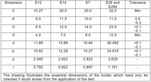 Replace the Table 3 with following: 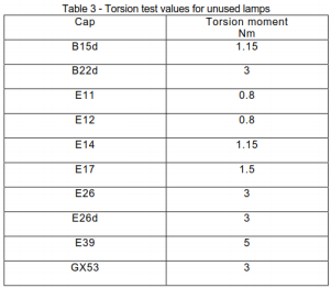 Replace the Table 5 with following: 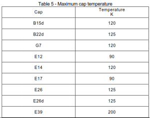 | N/A |
|---|
| ATTACHMENT TO TEST REPORT IEC 62368-1:2018 SAUDI ARABIA NATIONAL DIFFERENCES (Audio/video, information and communication technology equipment Part 1: Safety requirements) | |||
|---|---|---|---|
| Differences according to ............... : National standard SASO-IEC 62368-1:2020 | |||
| TRF template used:........................ : IECEE OD-2020-F3, Ed. 1.1 | |||
| Attachment Form No..................... : SA_ND_IEC62368_ 1E Attachment Originator................... : SASO Master Attachment......................... : 2022-12-22 | |||
| Copyright © 2022 IEC System for Conformity Testing and Certification of Electrical Equipment (IECEE), Geneva, Switzerland. All rights reserved. | |||
| National Differences | -- | ||
| Plugs used for pluggable equipment comply with standard SASO-2203. | N/A | ||
| -- | Frequency (Hz) | N/A | |
| 60 Hz | N/A | ||
| -- | Rated voltage (V) | N/A | |
| Single phase 230 V Three phase 400 V | N/A |
| ATTACHMENT TO TEST REPORT IEC 62368-1 SINGAPORE NATIONAL DIFFERENCES Audio/video, information and communication technology equipment-Part 1: Safety requirements | |||
|---|---|---|---|
| Differences according to ............... : Special National Conditions | |||
| TRF template used:........................ : IECEE OD-2020-F3, Ed. 1.1 | |||
| Attachment Form No..................... : SG_ND_IEC62368_ 1E Attachment Originator................... : Intertek Testing Services (Singapore) Pte Ltd Master Attachment......................... : 2022-07-08 | |||
| Copyright © 2022 IEC System for Conformity Testing and Certification of Electrical Equipment (IECEE), Geneva, Switzerland. All rights reserved. | |||
| National Differences | -- | ||
| Not Applicable | -- | ||
| Chapter 4.2 | Special national conditions (if any) Controlled goods under the Consumer Protection (Safety Requirements) Registration Scheme (CPS) are required to be tested to additional requirements stipulated by the Consumer Product Safety Office (CPSO) of Enterprise Singapore in Chapter 7 of the CPS information booklet. The CPS information booklet is updated on an ongoing basis. At the point of testing, refer to the latest copy of the CPS information booklet for the minimum edition of standard to apply for testing of products under the CPS scheme and any new requirements. Link to CPS information booklet: https://www.consumerproductsafety.gov.sg/files/cps-info-booklet. pdf | P | |
| Clause 1 | All appliances must be tested to 230 VAC, 50 Hz. | Not directly connected to mains | N/A |
| 4 | Appliance fitted with voltage selector shall be tested as follows: Connect appliance to 230 VAC mains with voltageselector switch to settings not suitable for operation at 230 VAC. | N/A | |
| 5 | All appliances (with tropical test requirements inapplicable Standards) shall comply with the tropical condition test as stated in the relevant IEC Standards. | N/A |
| 7 | All Class I appliances must be fitted with 3-pin mains plugs that are registered with the CPSO. | N/A | |
|---|---|---|---|
| 8 | a) All Class II appliances must be fitted with 2-pin mains plug complying with EN 50075. b) Class II appliances that are fitted with 3-pin mains plugs must use plugs that are registered with the CPSO. | N/A | |
| 9 | Detachable power cord set must be listed in the test report critical component list. | N/A | |
| 14 | AC Adaptor incorporated with 13A socket-outlet tobe tested to additional tests clauses 13, 17 and 18 of SS 145 Part 3: 2020. | N/A | |
| 15 | Supplier who is supplying AC adaptors with detachable interchangeable plug pins must include with its products, written instructions to inform customer on the type of detachable interchangeable plug pins that are approved and suitable to use in Singapore. These instructions are to be submitted to the Conformity Assessment Body for verification when applying for Certificate of Conformity. | N/A | |
| 16 | For AC Adaptors supplied together with Personal Mobility Devices: 1. Registered Supplier to declare the model of the AC adaptor that is to be used with/ bundled together with the PMDs; 2. Registered Supplier to provide valid IEC 60950-1 or IEC 62368-1 test reports for certification and registration of the declared AC adaptor under the CPS scheme; and 3. Registered Supplier to provide the UL 2272 test report as supporting document, showing that the listed AC adaptor in the UL 2272 test report is the model declared to be used with/ bundled together with the PMDs. | N/A | |
| 18 | CD/ DVD ROMs (used in personal computers) to have test certificate showing that CD/DVD ROM drive has complied with IEC 60825-1. | N/A | |
| 19 | Modem card incorporated in the personal computer must be tested at set level (sub-clauses 5.1 & 6 of IEC 60950) or at component level. | N/A | |
| 20 | Powerline Ethernet Adaptor incorporated with 13A socket-outlet, to be tested to additional test clauses 13, 17 & 18 of SS 145 Part 3: 2020. | N/A | |
| Other additional requirements which may be included in Chapter 7 of the information booklet in ongoing basis at the time of testing. | N/A |
| G.9 | TABLE: Integrated circuit (IC) current limiters | P | |
|---|---|---|---|
| Sample 1 | 10000 cycles of turning enable pin on and off, with max. rated input voltage and max. rated output load, the test sample conditioned 3h at 25°C before test | After tested, the IC still can limit the current in accordance with its specification as applicable | P |
| Sample 2 | 1. 50 cycles of turning enable pin on and off, with max. rated input voltage and 0Ω II 470µF* output load, the test sample conditioned 3h at 70°C before test; 2. 50 cycles of turning enable pin on and off, with max. rated input voltage and 0Ω II 470µF* output load, the test sample conditioned 3h at-30°C before test | After tested, the IC still can limit the current in accordance with its specification as applicable | P |
| Sample 3 | 1. 50 cycles of turning input power pin on and off, enable pin held active, with max. rated input voltage and 0Ω II 470µF* output load, the test sample conditioned 3h at 70°C before test; 2. 50 cycles of turning input power pin on and off, enable pin held active, with max. rated input voltage and 0Ω II 470µF* output load, the test sample conditioned 3h at-30°C before test | After tested, the IC still can limit the current in accordance with its specification as applicable | P |
| Sample 4 | 50 cycles of output load change between open circuit and short circuit (0Ω), enable pin held active, with max. rated input voltage, the test sample conditioned 3h at 70°C before test. | After tested, the IC still can limit the current in accordance with its specification as applicable | P |
| Sample 5 | 50 cycles of turning enable pin on and off, with max. rated input voltage and 150% of max. output load, the test sample conditioned 3h at 25°C before test | After tested, the IC still can limit the current in accordance with its specification as applicable | P |
| Sample 6 | 50 cycles of turning input power pin on and off, enable pin held active, with max. rated input voltage and 150% of max. output load, the test sample conditioned 3h at 25°C before test | After tested, the IC still can limit the current in accordance with its specification as applicable | P |
| Supplementary information: | |||
| 1) *: II means that in parallel. 2) Temperature tolerance is ±2°C. 3) Sample conditioned 3 h before test. 4) The above tests are performed together with the ancillary circuits provided by IC manufacturer to simulated the charging operation mode. 5) Tested with JL7006F, JL7083G and JL7096D, the results as same. |
Details of: View 1 of IC (for models JL7006F, JL7003F, JL7003D, JL7006D, JL6973D, JL6976D)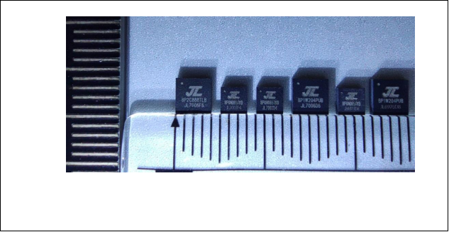 Details of: View 2 of IC (for models JL7006F, JL7003F, JL7003D, JL7006D, JL6973D, JL6976D)
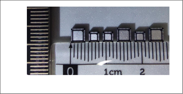 Details of: View 1 of IC (representative model JL7006F) mounted on the demo board
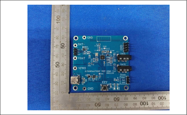 Details of: View 2 of IC (representative model JL7006F) mounted on the demo board
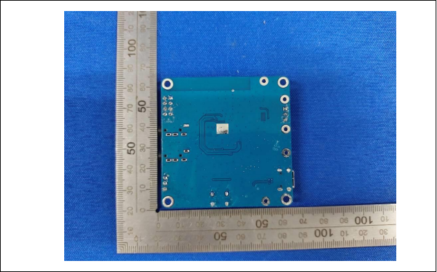 Details of: View 1 of IC (for models JL7083E, JL7083F, JL7083G, JL7086E, JL7086F, JL7086G)
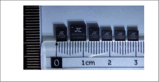 Details of: View 2 of IC (for models JL7083E, JL7083F, JL7083G, JL7086E, JL7086F, JL7086G)
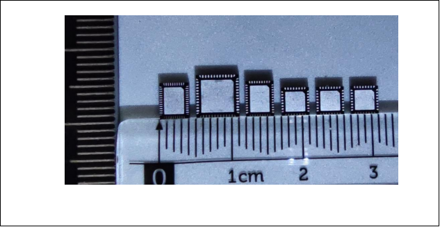 Details of: View 1 of IC (representative model JL7083G) mounted on the demo board
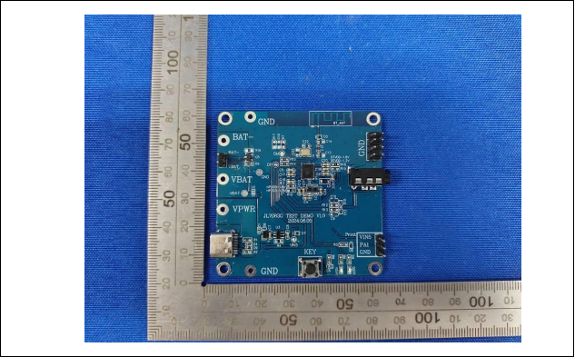 Details of: View 2 of IC (representative model JL7083G) mounted on the demo board
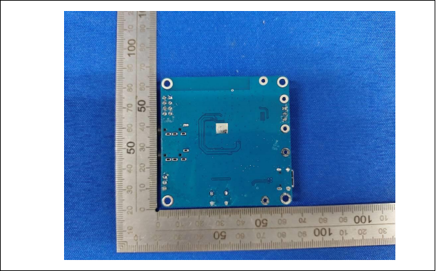 Details of: View 1 of IC (for models JL7096D, JL7096G, JL7096F, JL7094F, JL7094E, JL7094G, JL7093A, AC7196D)
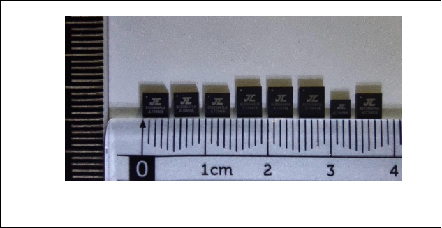 Details of: View 2 of IC (for models JL7096D, JL7096G, JL7096F, JL7094F, JL7094E, JL7094G, JL7093A, AC7196D)
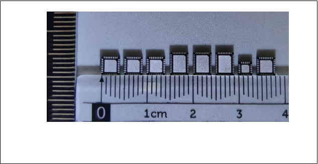 Details of: View 1 of IC (representative model JL7096D) mounted on the demo board
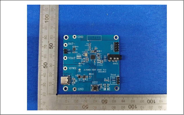 Details of: View 2 of IC (representative model JL7096D) mounted on the demo board
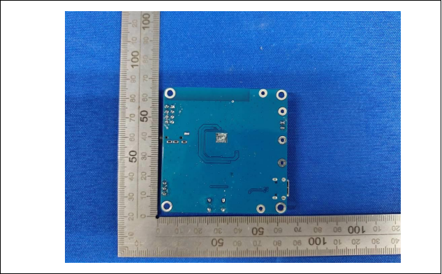 --END OF REPORT--